Image forming apparatus that prevents color deviation of image

Inactive Publication Date: 2001-05-22
KONICA MINOLTA INC
View PDF6 Cites 41 Cited by
  • Summary
  • Abstract
  • Description
  • Claims
  • Application Information

AI Technical Summary

Benefits of technology

is to provide an image forming apparatus that accurately correct color d

Problems solved by technology

This results in an extremely deteriorated image quality.
One of the biggest problems is how such color deviations can be reduced.
One reason is non-uniformity of refraction characteristics of scanning lenses provided for an optical scanning system that scans the laser beams across the photosensitive drums of the image forming units.
Another reason is inadequate adjustments to angles of redirecting mirrors.
However, if only these timings are controlled, color deviations caused from skews, bows, or variations in the scaling factors cannot be avoided.
However, using the method of changing the positions of the mirrors to avoid the color deviations caused from the variations in the scaling factor in the main scanning direction, the construction of the image forming apparatus increases in complexity and is

Method used


Image

  • Image forming apparatus that prevents color deviation of image
  • Image forming apparatus that prevents color deviation of image
  • Image forming apparatus that prevents color deviation of image

Examples


first embodiment

(1) Construction of the Copier

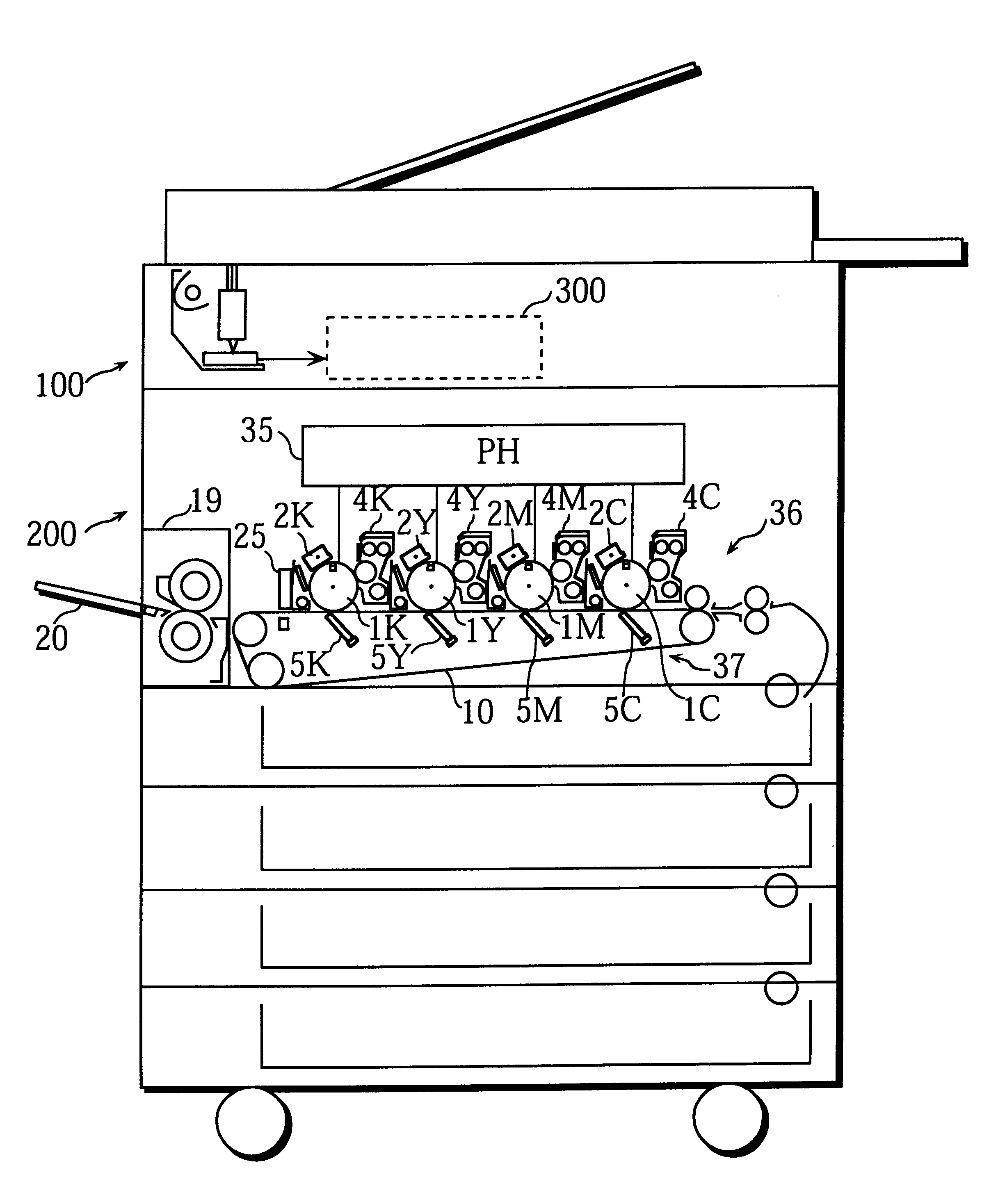
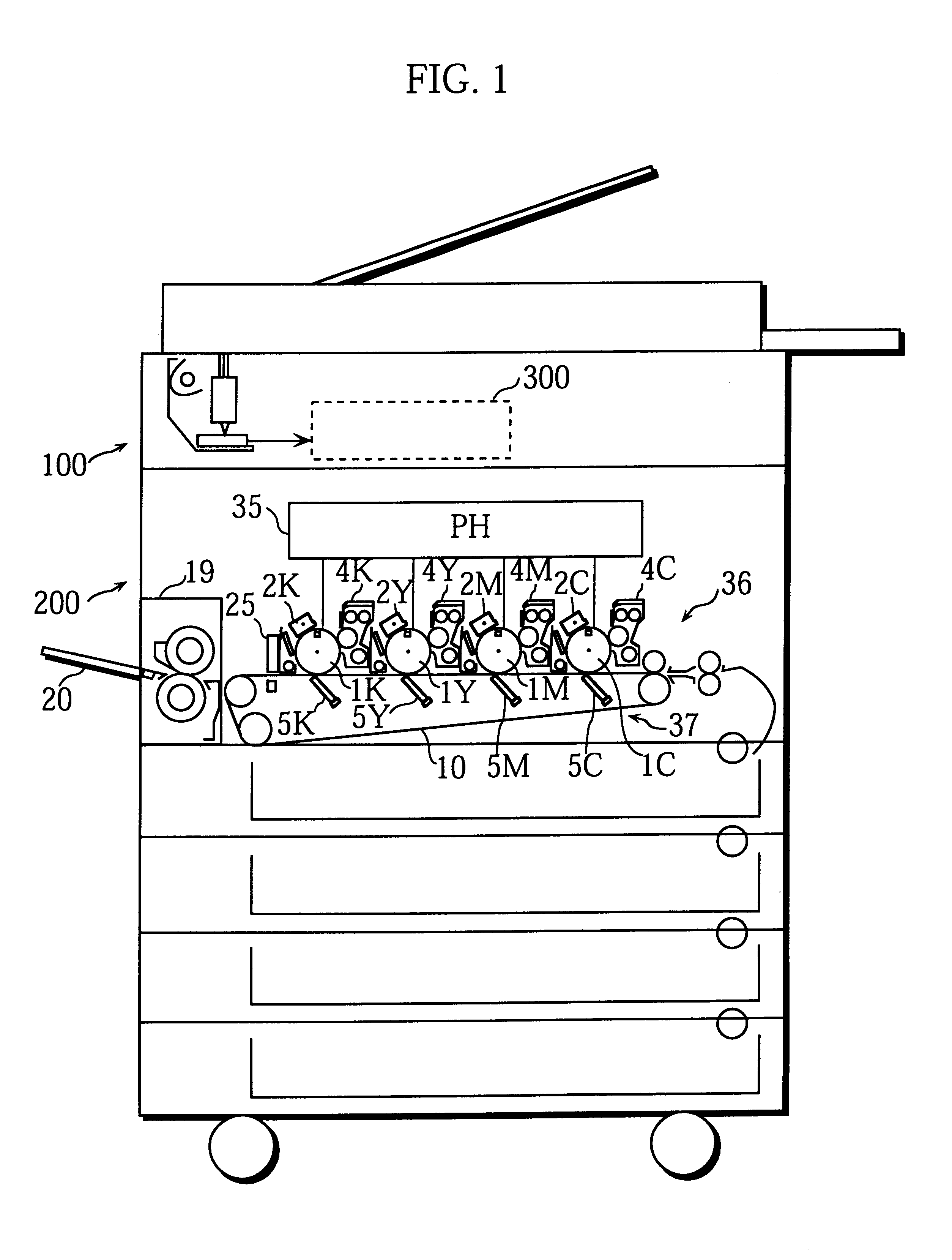
FIG. 1 is a schematic sectional view of the copier of the present embodiment. The copier has four image forming units set in line above a transfer belt along its length and forms a color image by transferring images formed by the image forming units onto a recording sheet.

As shown in FIG. 1, the copier is composed of an image reading unit 100 and a printing unit 200. The image reading unit 100 reads an image of a document and the printing unit 200 reproduces the image read by the image reading unit 100 on a recording sheet by printing. These two units are controlled by a control unit 300.

The image reading unit 100 is a well-known device that reads an image of a document set on a platen glass (not illustrated) and obtains multivalued digital signals for red (R), green (G), and blue (B). The obtained multivalued digital signals are next converted into 8-bit gradation data for C, M, Y, and K in the control unit 300. The control unit 300 performs various pr...

second embodiment

In the first embodiment, the amount of correction calculated according to the correction approximation function is converted into the amount of address correction to be made in the image memory 312. In accordance with the amount of address correction, a pixel (or, a target pixel) is determined whether it is printed or not at the original position. Here, a target pixel refers to a pixel before correction. In the determining operation, a pixel is switched between on (printed) and off (not printed) in the first embodiment. In other words, correction is performed in units of pixels. According to this method, however, an image noise may occur. This is because pixels are switched between on and off at almost the same position in the main scanning direction over a plurality of scanning lines.

To avoid this problem, in the second embodiment, a target pixel is not simply switched between on and off when the image forming position is corrected for each reproduction color. To be more specific, ...

third embodiment

In the third embodiment, the amount of correction is calculated using a function that is obtained by superposing a predetermined auxiliary function on the correction approximation function obtained according to the method explained in the first embodiment. The processing for calculating the amount of correction using this function is explained in the third embodiment. The processing is performed with the aim of preventing noise streaks from appearing when images for the reproduction colors are superimposed. The noise streaks are caused by tiers appearing in units of pixels as described in the second embodiment.

A more detailed explanation about noise streaks is given, with reference to FIG. 11. FIG. 11 is a drawing to help explain why the noise streaks occur to a reproduced image. It should be noted here that the density distribution processing described in the second embodiment has not been performed for the example shown in FIG. 11. The reproduction color used in this example may b...


PUM


Abstract

At least two registration marks are formed for each of the reproduction colors cyan, magenta, yellow, and black. Each of the marks for each color is formed at a different position in the main scanning direction. Each position of the marks is detected, and the deviation is obtained for each color from the detection result. Using the obtained deviations, a correction approximation function is formulated that is used for determining writing positions for pixels of an image. In accordance with the correction approximation function, an image writing position at which an image forming unit starts writing is corrected, so that color deviations caused from various factors can be prevented.

Description

(1) Field of the InventionThe present invention relates to an image forming apparatus that prevents color deviations from occurring to a reproduced image.(2) Description of Related ArtIn general, when a color image is formed using a full-color image forming apparatus, data of an image to be formed is divided into reproduction colors cyan, magenta, yellow, and black. A toner image is first formed for each reproduction color, and then a color image is formed by transferring the toner images onto, for example, a recording sheet. If image forming positions for the colors are deviated from one another, color deviations occur to a reproduced color image. This results in an extremely deteriorated image quality. Hereinafter, the reproduction colors are respectively referred to as C, M, Y, and K and components related to these colors are assigned numerals with a corresponding C, M, Y, or K.As one example of a conventional full-color image forming apparatus, there are so-called "tandem-type" ...

Claims


Application Information

Patent Timeline
IPC IPC(8): H04N1/50H04N1/04G03G15/00G03G15/01
CPCH04N1/506G03G2215/0119G03G2215/0161
Inventor HADA, YOSHINOBU
Owner KONICA MINOLTA INC
Why Eureka
Try Eureka