Fixing device

a fixing device and surface technology, applied in the direction of thin material processing, electrographic process equipment, instruments, etc., can solve the problems of partial wear and scratching the surfa

Inactive Publication Date: 2001-05-22
FUJIFILM BUSINESS INNOVATION CORP
View PDF6 Cites 13 Cited by
  • Summary
  • Abstract
  • Description
  • Claims
  • Application Information

AI Technical Summary

Benefits of technology

]As described above, according to the first fixing device of the present invention, the first rotator is formed with an elastic layer on the surface, and there is provided a peeling sheet for peeling a sheet from the first rotator by causing its end edge to come into contact with the surface of the first rotator, downstream of the nip portion in the direction of rotation of the first rotator, whereby it is possible to realize a fixing device having a peeling sheet capable of stably peeling a non-fixed toner image formed by transferring a large amount of toner as in the case of color fixing, without causing any damage to the toner image, the sheet, and the first rotator.Also, according to the second fixing device of the present invention, there is provided a peeling sheet, comprising: a contact portion, of the first rotator, for contacting the surface of the first rotator, downstream of the nip portion of the first rotator in the direction of rotation thereof; and a tip end portion having a shape further extending upstream of the contact portion in the direction of rotation of the first rotator, and extending on the upstream side, arranged spaced apart a predetermined interval from the surface of the first rotator, whereby it is possible to realize a fixing device having a peeling sheet capable of stably peeling a non-fixed toner image on the surface of the first rotator without causing any damage to the toner image, the sheet and the first rotator as in the case of the first fixing device according to the present invention.

Problems solved by technology

However, even if such a fixing roller is used, the fused toner easily adheres to the surface of the fixing roller because it is soft and highly viscous, and the sheet may wind around the fixing roller.
Also, in a case where the sheet hooks on any one of the plurality of peeling claws to cause winding of the sheet, the adjacent peeling claws may receive an unusual force caused by the sheet to be strongly pressed against the fixing roller 1, or to be deformed, thus seriously scratching the surface of the fixing roller 1 or causing partial wear.

Method used


Image

  • Fixing device
  • Fixing device
  • Fixing device

Examples


first embodiment

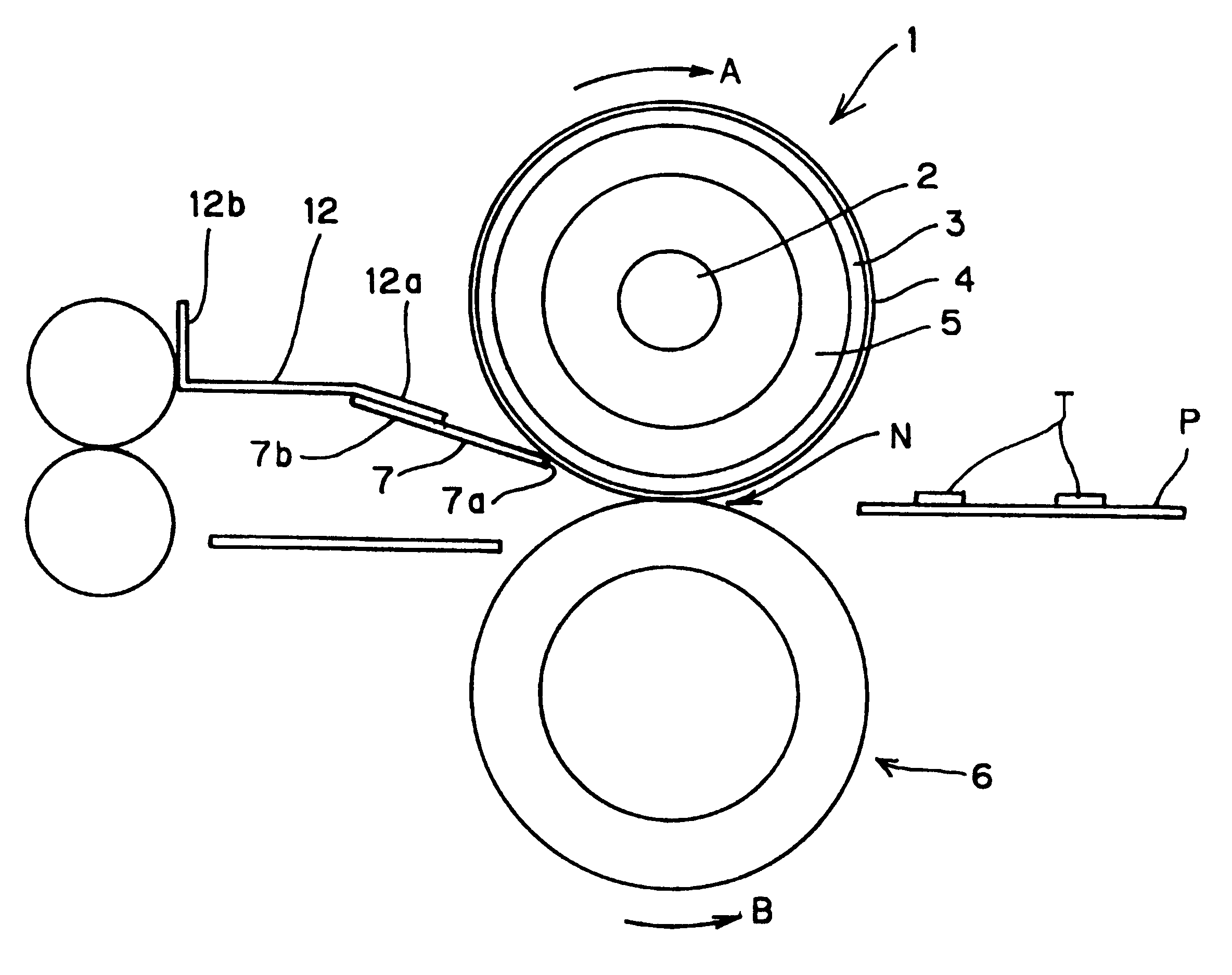
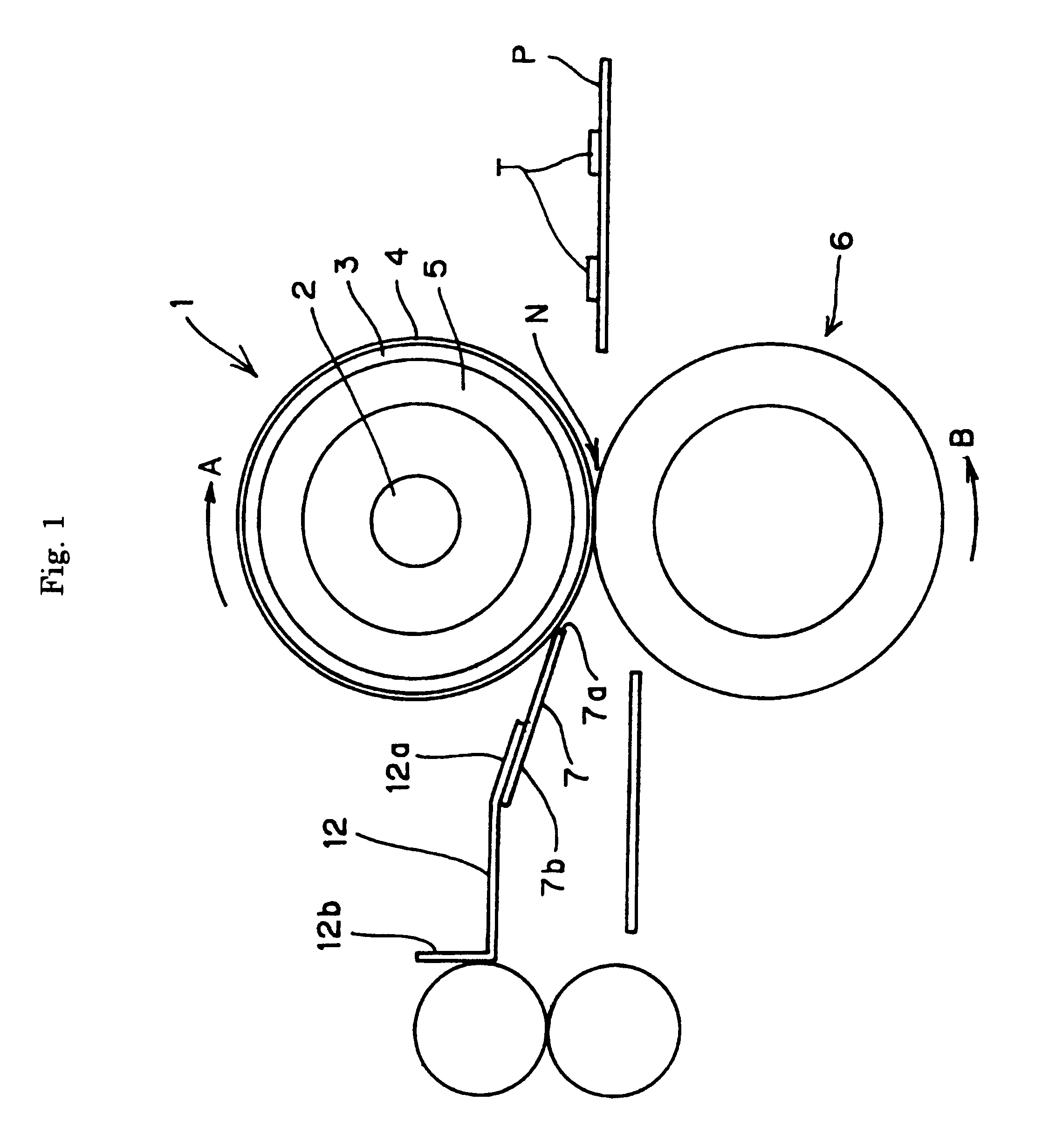
FIG. 1 is a schematic structural view showing a fixing device according to the present invention;

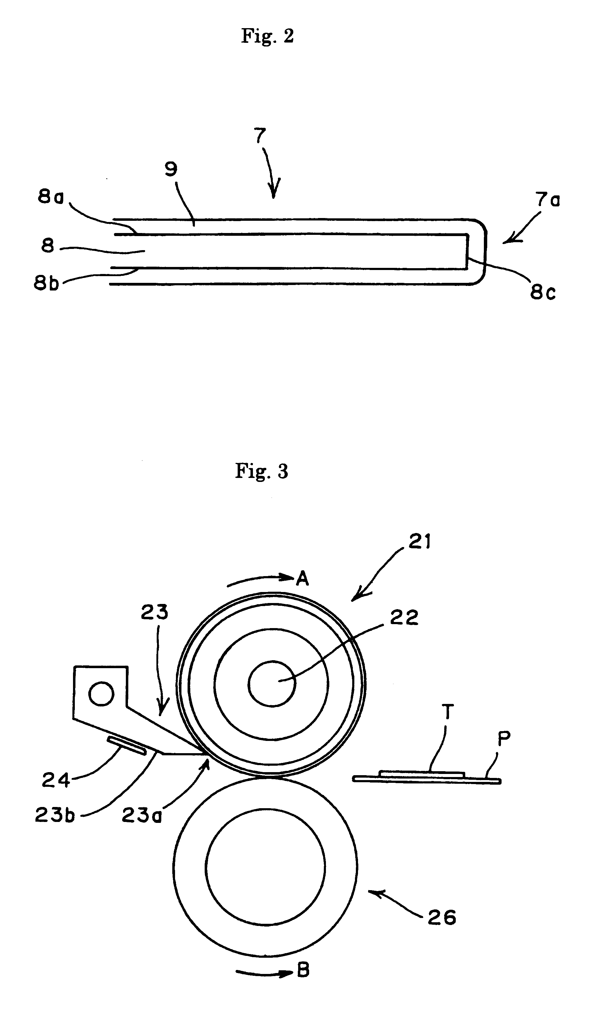
FIG. 2 is a cross-sectional view showing a peeling sheet provided for a fixing device according to the first embodiment;

FIG. 3 is a schematic structural view showing a peeling force measuring apparatus;

FIG. 4 is a cross-sectional view showing a peeling sheet used for a second fixing device according to the present invention;

FIG. 5 is a view showing a variation of the peeling sheet shown in FIG. 4;

third embodiment

FIG. 6 is a cross-sectional view showing a peeling sheet used for a third embodiment according to the present invention;

FIG. 7 is a plan view showing the peeling sheet shown in FIG. 6;

FIG. 8 is a plan view showing a variation of the peeling sheet according to the third embodiment;

FIG. 9 is a plan view showing another variation of the peeling sheet according to the third embodiment;

FIG. 10 is a schematic structural view showing a conventional fixing device having a forced peeling device using peeling claws;

FIG. 11 is a schematic structural view showing a conventional fixing device having a forced peeling device using a plastic peeling sheet;

FIG. 12 is a table showing experimental results of the maximum peeling force when a hard roller with flourine resin is used as the fixing roller;

FIG. 13 is a table showing experimental results of the maximum peeling force when color fixing was performed using, as the fixing roller, a soft roller with a coating of silicone rubber of thickness 0.1 m...

second embodiment

In this respect, the following peeling sheet may be used as a variation of the

FIG. 5 is a view showing a variation of the peeling sheet shown in FIG. 4.

As shown in FIG. 5, this peeling sheet 13' uses, as in the case of the peeling sheet 13 shown in FIG. 4, a heat-resistant plastic sheet or a metallic sheet, on one side of which a fluorine resin layer 19 is formed, as a base member 18, and is formed as a laminated member obtained by folding the base member 18 into two leaves with the surface having the fluorine resin layer 19 formed thereon, placed on the outside. Spherical or cylindrical particles 20 having a diameter of 5 to 100 .mu.m are caused to be interposed between two portions obtained by thus folding the base member 18 into two leaves, whereby a bulge is produced along an end edge 13a' of the peeling sheet 13' on the side on which the fold has been formed to form a contact portion 15' slightly larger than the contact portion 15 in the peeling sheet 13 shown in FIG. 4. The pa...


PUM


Abstract

A fixing device having a peeling sheet capable of performing stable peeling without causing any damage to the image, the sheet, and the fixing roller. A fixing device, including: a fixing roller having an elastic layer formed on the surface thereof which rotates in a direction indicated by an arrow A; a compression roller which rotates in a direction indicated by an arrow B while being in contact with the fixing roller; and a plastic peeling sheet, whose end edge comes into contact with the surface of the fixing roller to peel the sheet P, which has passed through the nip portion N, away from the surface of the fixing roller, provided downstream of the nip portion N of the fixing roller in the direction of rotation A thereof.

Description

[Detailed Description of the Invention]1. Technical Field of the InventionThe present invention relates to a fixing device for use in an image recording apparatus of the electrophotographic type such as an electronic copying machine or a facsimile.2. Prior ArtConventionally, in an image recording apparatus of the electrophotographic type such as an electronic copying machine or a facsimile, there is widely used a fixing device in which a sheet having a toner image transferred thereto is passed through a nip portion between a pair of rollers consisting of a fixing roller and a compression roller to thereby fuse the toner image to the sheet by means of heating by the fixing roller and compression by the two rollers.Generally, in this fixing method, since the toner image fused to the sheet comes into contact with the fixing roller, a roller having a fluorine resin coating layer with high mold release characteristics is used. However, even if such a fixing roller is used, the fused tone...

Claims


Application Information

Patent Timeline
Patent Type & Authority Patents(United States)
IPC IPC(8): G03G15/20B65H29/54
CPCG03G15/2028
Inventor UEHARA, YASUHIROKANESAWA, YOSHIO
Owner FUJIFILM BUSINESS INNOVATION CORP
Why Eureka
Try Eureka