
Paper towel transfer apparatus

a technology of paper towel and transfer device, which is applied in the field of paper towel transfer device, can solve the problems of inconvenient installation, difficult teaching of procedures, and increased risk of breakage, and achieve the effect of saving costs and being easy to install

Inactive Publication Date: 2001-05-29
DISPENSING DYNAMICS INT
View PDF20 Cites 81 Cited by
  • Summary
  • Abstract
  • Description
  • Claims
  • Application Information

AI Technical Summary

Benefits of technology

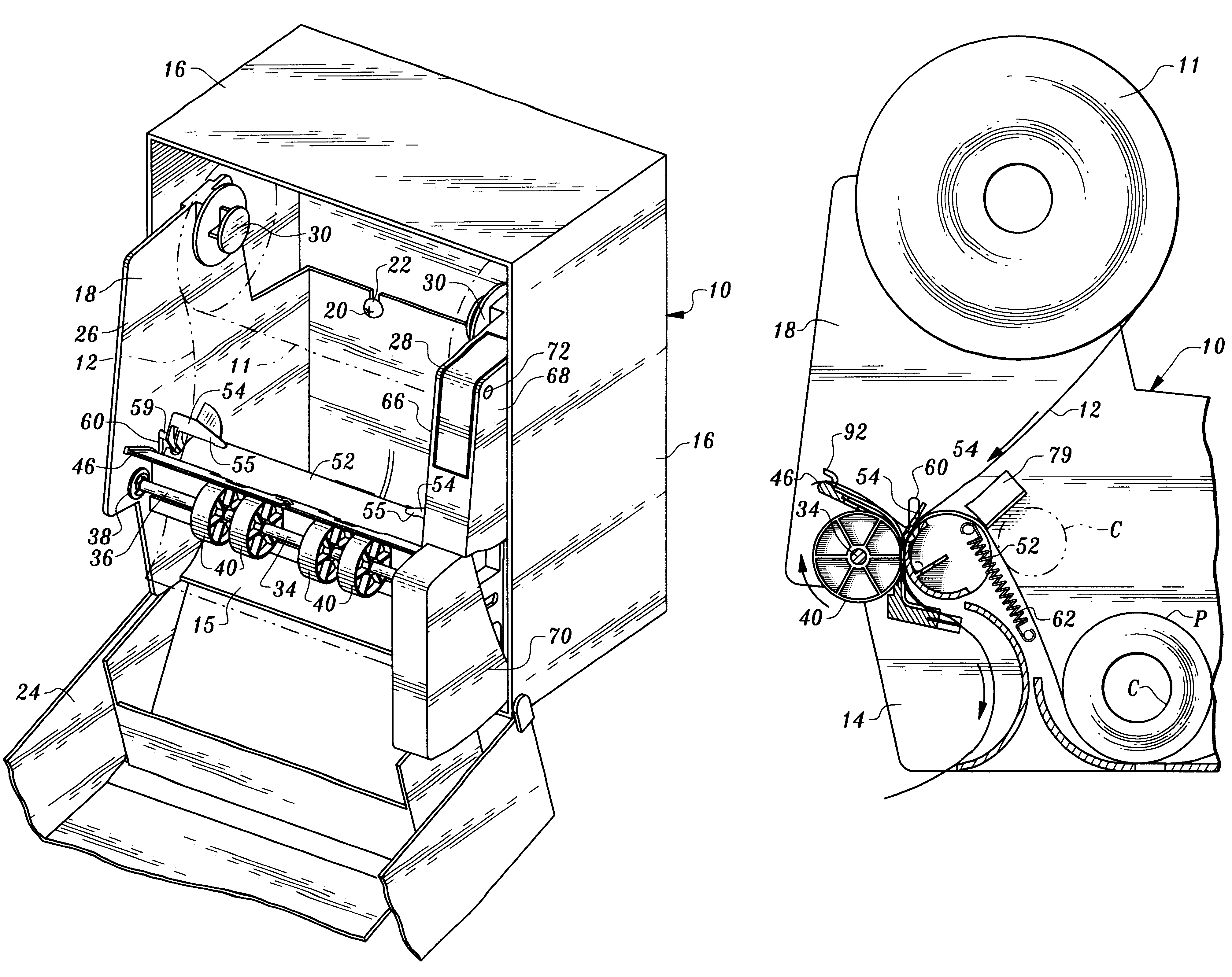
The apparatus disclosed and claimed herein represents an improvement of the system of our co-pending U.S. patent application Ser. No. 09 / 164,440, particularly with regard to roll transfer. More particularly, a pair of tucker members are employed in the arrangement of the present invention and the tucker members are readily installed even after the dispenser has been assembled. The dispenser can be shipped without any transfer device to save cost and allow addition of the transfer mechanism at a later time.
In addition, the arrangement disclosed herein loads much more readily. In the prior arrangement, the elongated tucker element or bar can get in the way when the user is trying to load a full roll. In addition, the tucker disclosed in our co-pending application, due to its length, was more susceptible to breakage. The present arrangement is highly reliable and not prone to damage. In addition, in the former arrangement springs were connected to the tucker member or bar to enable it to work satisfactorily. These springs were positioned where they could be inadvertently hit and damaged. Also, some difficulties were presented by the fact that proper loading of and positioning of paper was not obvious and the procedure could be difficult to teach. While springs are employed in the arrangement disclosed and claimed herein, they are out of the way and not prone to inadvertent contact. Assembly is simplified and assembly costs are lowered.

Problems solved by technology

In addition, the tucker disclosed in our co-pending application, due to its length, was more susceptible to breakage.
These springs were positioned where they could be inadvertently hit and damaged.
Also, some difficulties were presented by the fact that proper loading of and positioning of paper was not obvious and the procedure could be difficult to teach.

Method used


Image

  • Paper towel transfer apparatus
  • Paper towel transfer apparatus
  • Paper towel transfer apparatus

Examples


Embodiment Construction

Referring now to the drawings, apparatus constructed in accordance with the teachings of the present invention is illustrated.

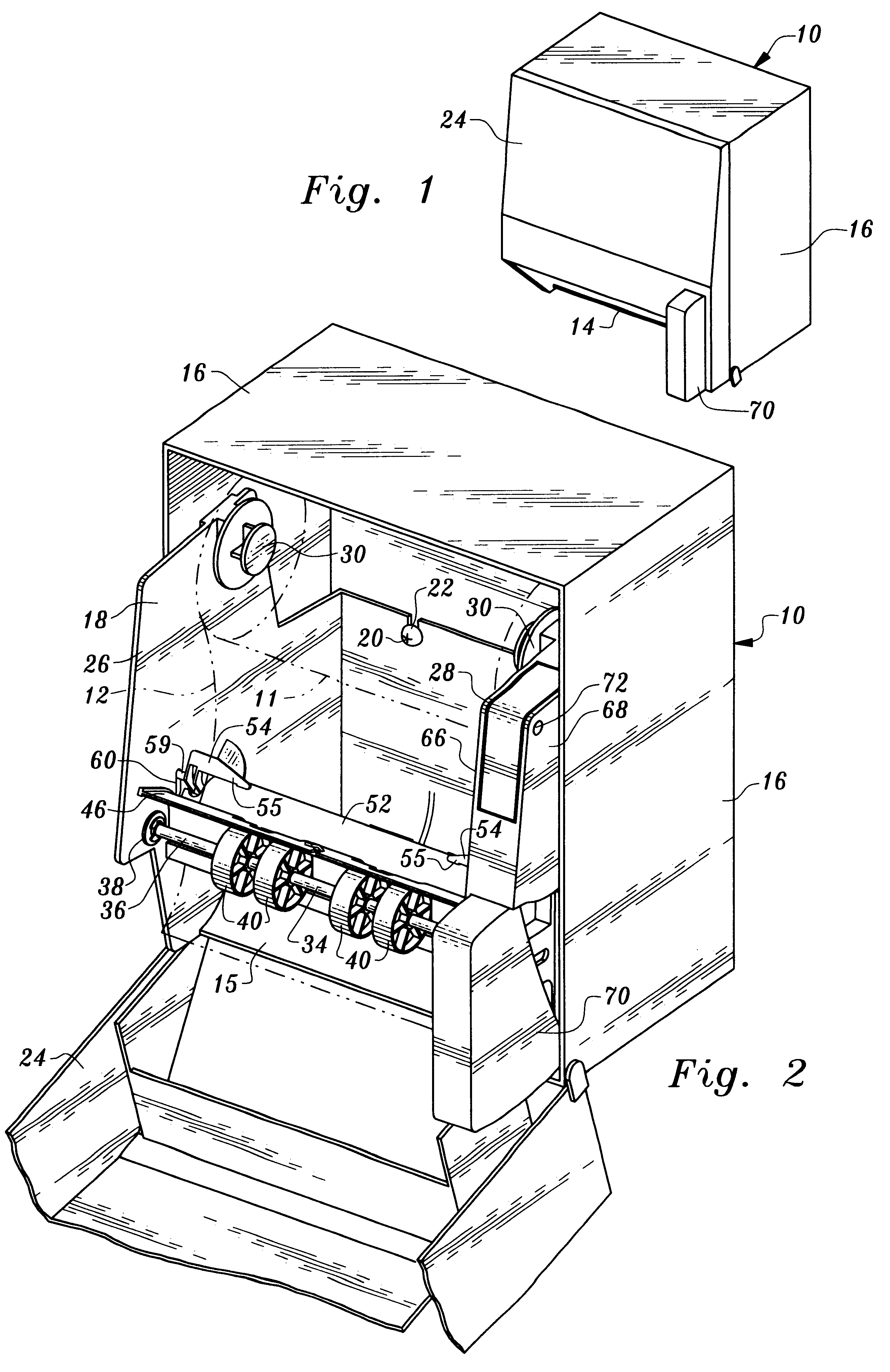
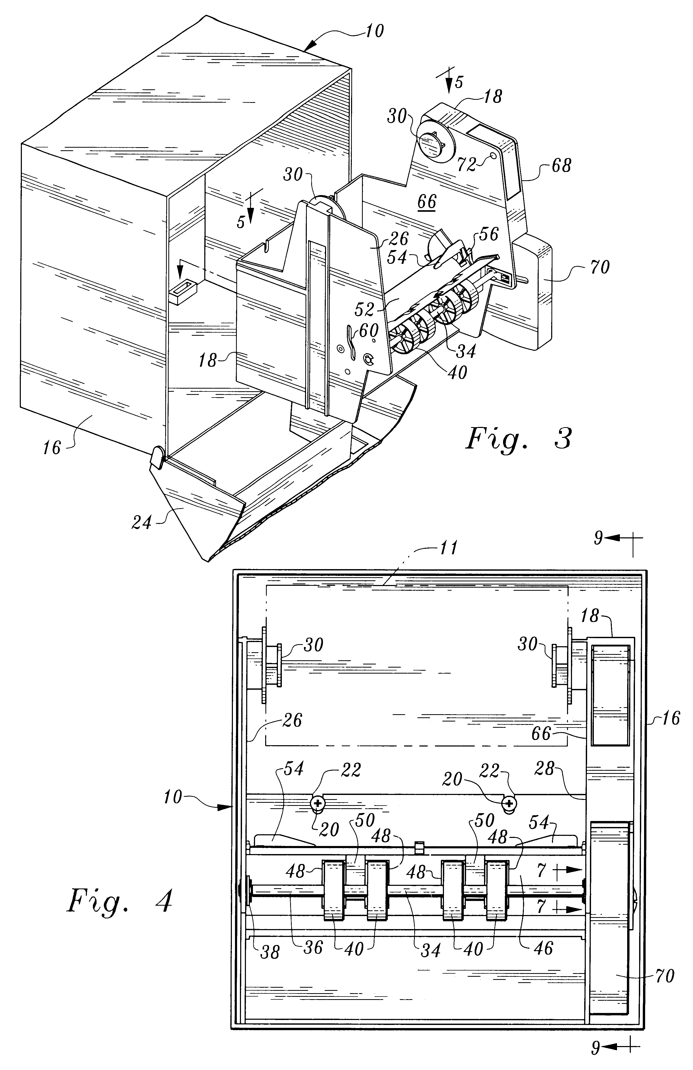
The apparatus includes a housing 10 defining an interior for accommodating a roll of sheet material in the form of a roll 11 of paper toweling 12. The housing has an outlet 14 communicating with the housing interior. A curved plate 15 leads to outlet 14.

In the arrangement illustrated, the housing includes an outer housing segment 16 and an inner housing segment 18. These housing segments may be releasably connected together by any suitable means such as threaded fasteners 20 on the outer housing segment received in recesses 22 of the inner housing segment. The disclosed arrangement allows ready connection and disconnection of the housing segments. Outer housing segment 16 includes a hingedly mounted cover 24.

Inner housing segment 18 includes side walls 26, 28. Attached to these side walls are projections 30 which are insertable into the ends of a paper towel ...


PUM


Abstract

Apparatus for dispensing sheet material from a roll of sheet material includes a rotatable sheet material engagement member having an outer surface for engaging the sheet material. A pivoted shaft is mounted adjacent to the sheet material engagement member having a feed roller mounted thereon. The shaft and feed roller are pivotally moved toward the sheet material engagement member and the feed roller is rotated to transport the sheet material over the outer surface of the sheet material engagement member. Spaced tucker members are connected to the sheet material engagement member and simultaneously rotate and pivot upon depletion of a primary roll of sheet material to position the lead end of a reserve roll between the sheet material engagement member and the feed roller.

Description

This invention relates to apparatus for dispensing sheet material from a roll of sheet material. The invention is particularly applicable to the dispensing of paper toweling and the apparatus provides for the automatic transfer from a depleted towel roll to a reserve roll.A great many systems have been devised over the years for dispensing paper toweling from rolls thereof. Many of these systems employ rotatable feed rollers which engage the toweling and direct the toweling to a position exterior of a cabinet or housing for delivery to the consumer. A wide variety of mechanisms have been devised to cause and control rotation of the feed roller as well as severance of the individual towel sheets from the toweling unwound from the roll.With respect to feed roller actuation and rotation, the use of one-way clutch mechanisms is not uncommon, such mechanisms being utilized to ensure rotation of feed rollers in only one direction of rotation upon actuation of the dispenser mechanism by th...

Claims


Application Information

Patent Timeline
IPC IPC(8): A47K10/36A47K10/24
CPCA47K10/36A47K10/3656A47K10/3687A47K2010/3681
Inventor MORAND, MICHELPERRIN, PATRICK C.VAN DE BRAKE, ARTHUR
Owner DISPENSING DYNAMICS INT
Learn More