
Producing colored light beams from white light

Inactive Publication Date: 2001-05-29
DUKE UNIV
View PDF3 Cites 28 Cited by
  • Summary
  • Abstract
  • Description
  • Claims
  • Application Information

AI Technical Summary

Problems solved by technology

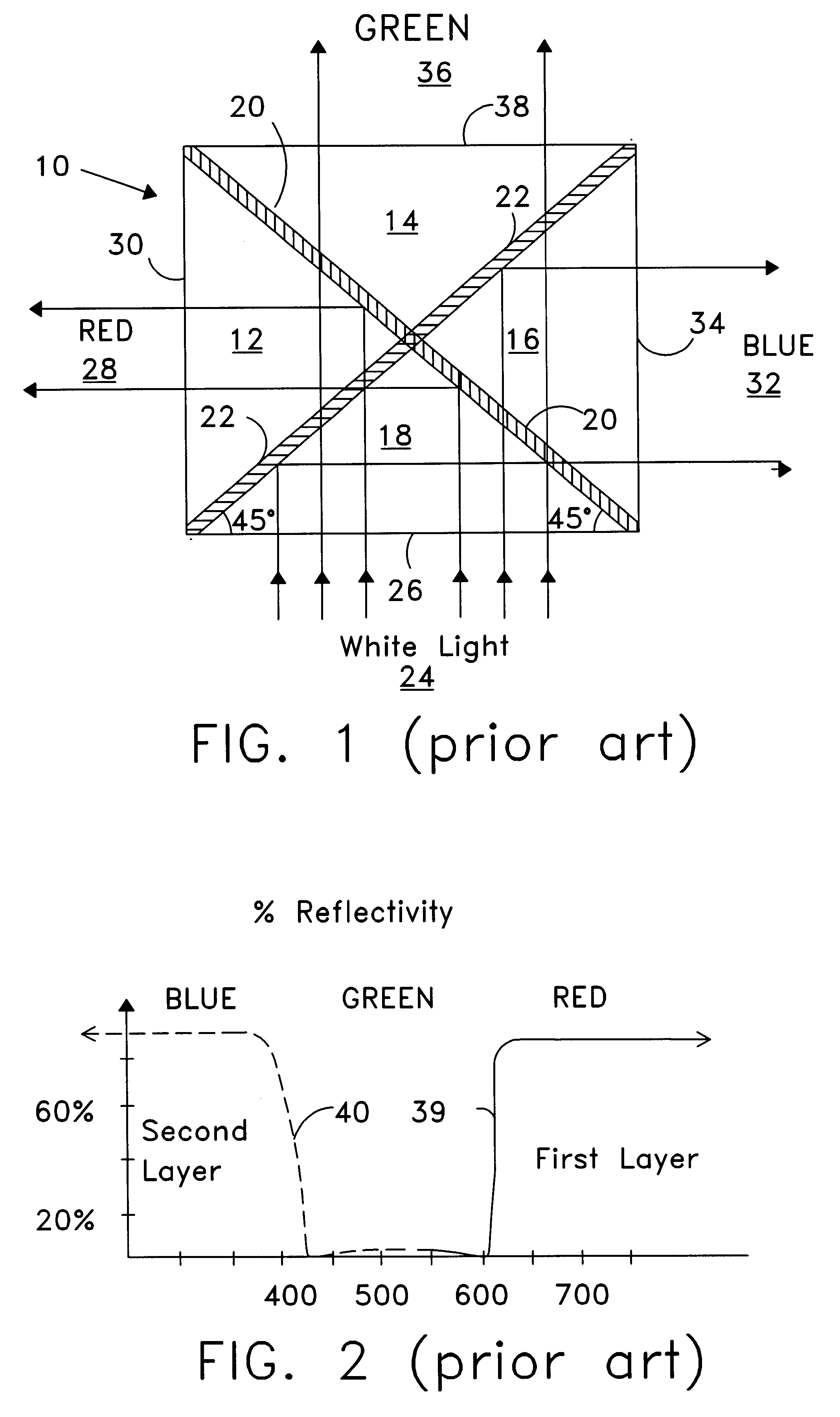
Moreover, for the cross cube 10, another disadvantage is that the center of the "X" may be projected (e.g., in a projection system) to a screen and seen as a line to a viewer of the screen.

Method used


Image

  • Producing colored light beams from white light
  • Producing colored light beams from white light
  • Producing colored light beams from white light

Examples


Embodiment Construction

Specific embodiments of the invention are described below. In the interest of clarity, not all features of an actual implementation are described in this specification. It will of course be appreciated that in the development of any such actual embodiment, numerous implementation-specific decisions must be made to achieve the developers' specific goals, such as compliance with system-related and business-related constraints, which will vary from one implementation to another. Moreover, it will be appreciated that such a development effort might be complex and time-consuming, but would nevertheless be a routine undertaking for those of ordinary skill in the art having the benefit of this disclosure.

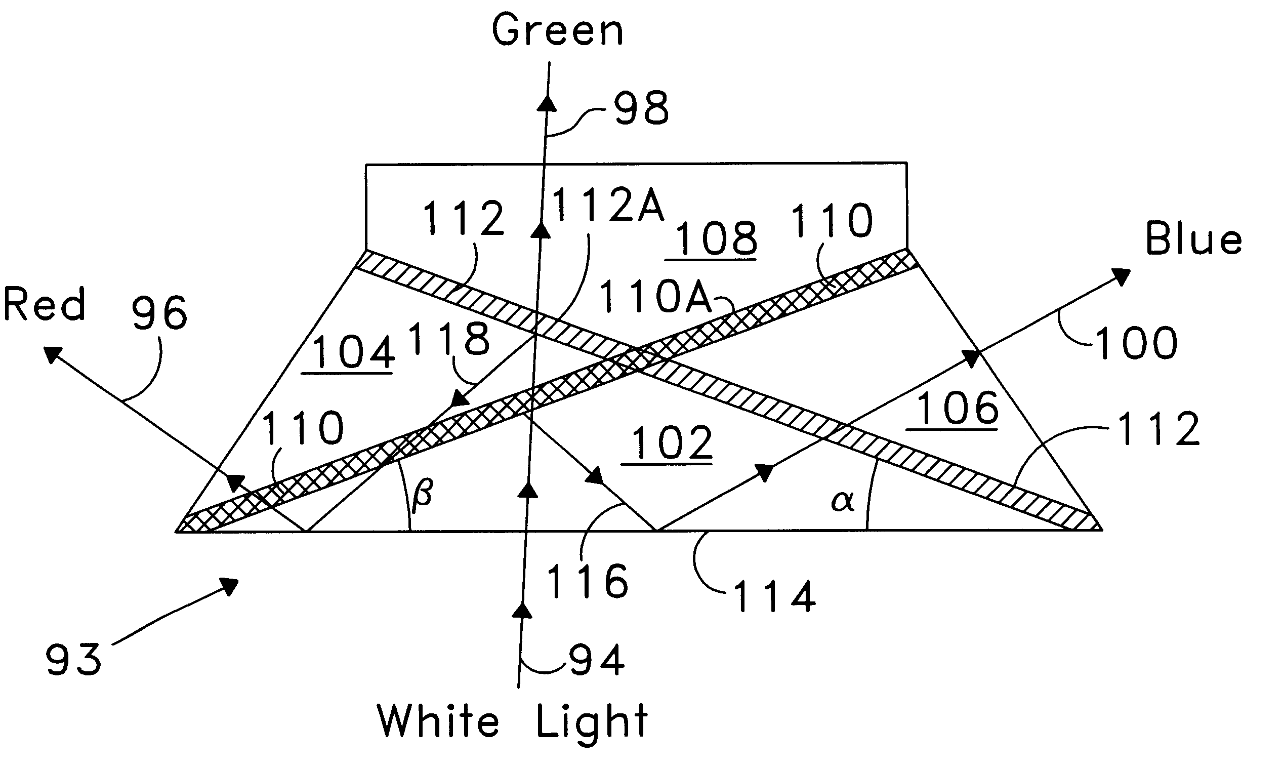
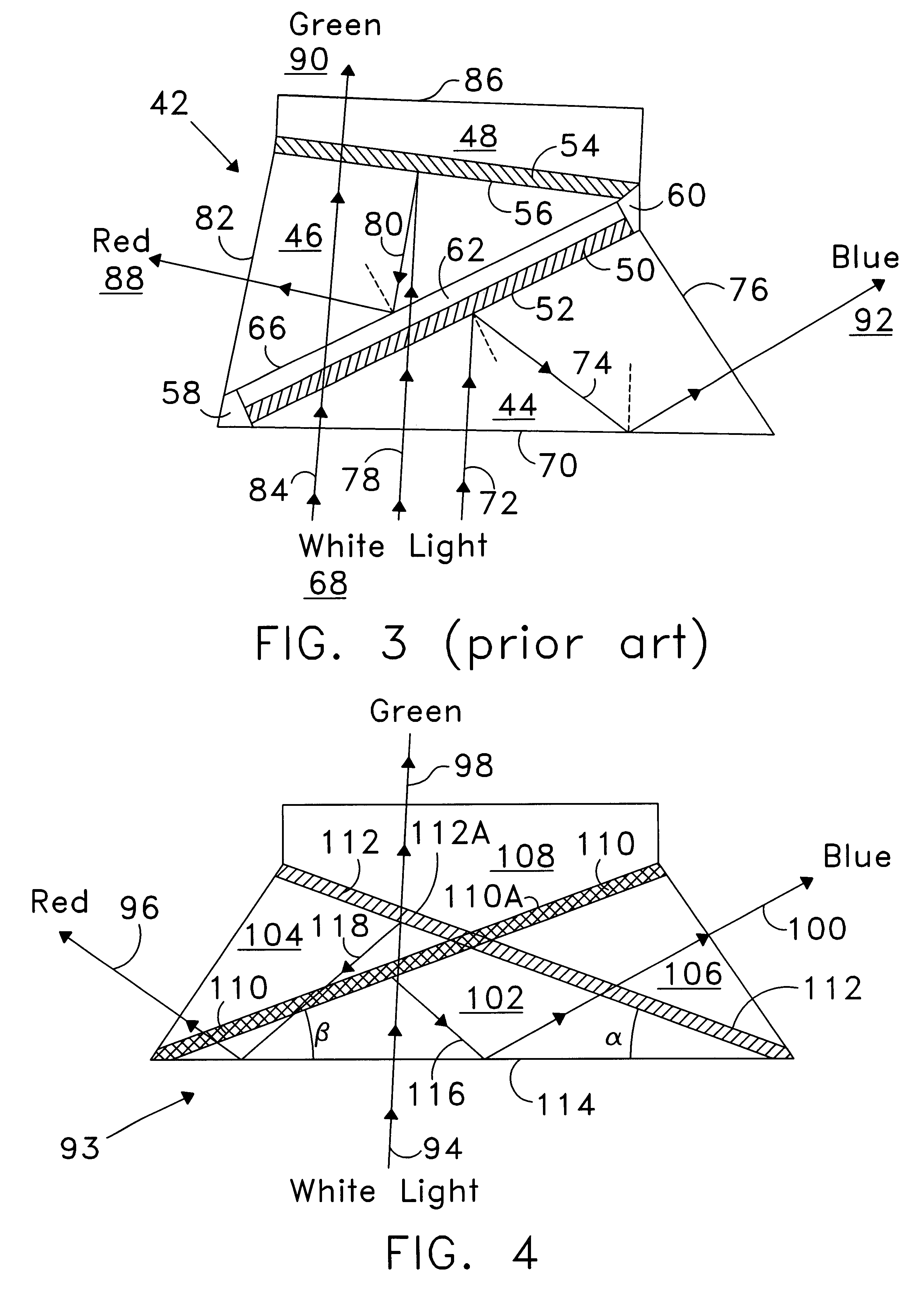
FIG. 4 illustrates a prism 93 that separates an incoming white or quasi-white light beam 94 into three colored light beams 96, 98, 100 in accordance with an embodiment of the invention. Three component prisms 102, 104, 106 and a cover element 108 form a body of the prism 93. The component ...


PUM


Abstract

A color-separating prism includes first, second, and third component prisms that form first and second adjacent pairs of faces and include nonadjacent faces. The third component prism has a front surface or face. The color-separating prism includes a first reflective layer disposed in part between the first adjacent pair of faces and in part on one nonadjacent face and a second reflective layer disposed in part between the second adjacent pair of faces and in part on another nonadjacent face. The first and second reflective layers are inclined to reflect portions of light incident on the front surface back toward the front surface for total internal reflection. The color-separating may be used to produce narrow-spectral light from broader spectral light. A first portion of a light beam substantially in a first wavelength range is reflected from the first reflective layer back toward the front face of the prism. A second portion of the light beam substantially in a second wavelength range is reflected from the second reflective layer back toward the front face of the prism. The first and second portions are totally internally reflected from the front face. The color-separating prism can be used in display systems.

Description

1. Field of the InventionThe present invention relates generally to optical devices and prisms, and, more particularly, to separating a white light beam into several colored light beams.2. Description of the Related ArtFIG. 1 illustrates a color-separating prism based on a cross cube 10. The cross cube 10 has a square cross section and is composed of four glass prisms 12, 14, 16, 18. A first reflective layer 20 lies along a first principal diagonal of the cross cube 10. A second reflective layer 22 lies along a second principal diagonal, and intersects the first layer 20 at a right angle. The first and second reflective layers 20, 22 are multi-layers of dichroic material that selectively reflect certain wavelength or color ranges of light.Referring to FIG. 1, a white light beam 24 enters the cross cube 10 through a first face 26 and is selectively reflected by the first and second reflective layers 20, 22. The first reflective layer 20 reflects red light 28 from the incoming white l...

Claims


Application Information

Patent Timeline
Patent Type & Authority Patents(United States)
IPC IPC(8): G03B21/14
CPCG03B21/14G03B21/005G03B21/2066G03B21/28G03B33/12
Inventor HUANG, AUSTIN L.
Owner DUKE UNIV
Learn More