Cable reel having slip ring capsule and overwinding protection

a cable reel and capsule technology, applied in the field of cable reels, can solve the problems of cable damage, unwieldy handling and storage of cable reels, and damage to cables, and achieve the effect of avoiding the need for discarding of damaged cables

Inactive Publication Date: 2001-06-05
VAN ESS QUENTIN W +1
View PDF6 Cites 21 Cited by
  • Summary
  • Abstract
  • Description
  • Claims
  • Application Information

AI Technical Summary

Benefits of technology

In a broad embodiment, the present invention involves a cable reel comprising a support frame having an elongated shaft projecting therefrom, the shaft having a central axial aperture extending therethrough; a slip ring capsule disposed at an end of the shaft distal to the frame. the slip ring capsule having a rotor and a stator in mutual electrical contact, the stator being fixed to the shaft; a reel having a hub comprising a hollow drum with lateral sides projecting radially therefrom, with the hub mounted on the shaft for rotation therearound and the sides having sufficient height to contain a communication cable therebetween wound on the hub; mechanical and termination junction means for mechanical and continuity attachment of one end of the communication cable to an outer side of the hollow drum, with the termination junction means further comprising a first communication circuit from the attachment to the one end of the communication cable through a wall of the hollow drum to communication connection with the rotor of the slip ring capsule; a second communication circuit extending through the central aperture of the shaft and having terminal connection to the stator of the slip ring; driving means for alternately rotating the reel about the shaft in a first direction to pay out a cable contained thereon and attached thereto and for rotating the reel about the shaft in an opposite second direction to retrieve paid out cable for containment on the reel; and overwinding protection means for preventing the driving means from being overwound when rotating in either direction; such that the slip ring capsule maintains full continuity between the first and second communication circuits while the reel is rotating and the driving means and the clutch means cooperate during retrieval of paid out communication cable to permit rapid retrieval of the cable without overwinding of the driving means.
Also part of the invention are a strain relief element to prevent strain on the communication cable where it plugs into the connector with the aircraft's communication system, and a protective device into which the connection end of the cable retracts when not in use, to prevent damage if the end of the cable strikes the tarmac or adjacent equipment.

Problems solved by technology

The cables are unwieldy for the tug driver or other ground crew members to handle and store.
Since they have no permanent connections, it is common for cables which are not in use to be left lying on the tarmac or thrown across other pieces of ground equipment, resulting in frequent damage to the cables.
The damage is usually severe enough to require discarding of the damaged cables.
Since the cables are expensive, the cost to airlines of cable replacement are high.
However, in the past that has not proved feasible because stowage was difficult and time-consuming, so ground crews were often unable or unwilling to perform the stowage correctly.
In addition, since the cable must be moved before and after connection to the airplane, and ground crews are frequently less than careful in their handling of the cable, it has been difficult with prior art equipment to maintain a good communication connection of the cable to the tug for any extended period of time, since rough handling has often damaged the connection equipment.
Nothing in the prior art has heretofore been capable of providing such useful and functional devices.

Method used


Image

  • Cable reel having slip ring capsule and overwinding protection
  • Cable reel having slip ring capsule and overwinding protection
  • Cable reel having slip ring capsule and overwinding protection

Examples


Embodiment Construction

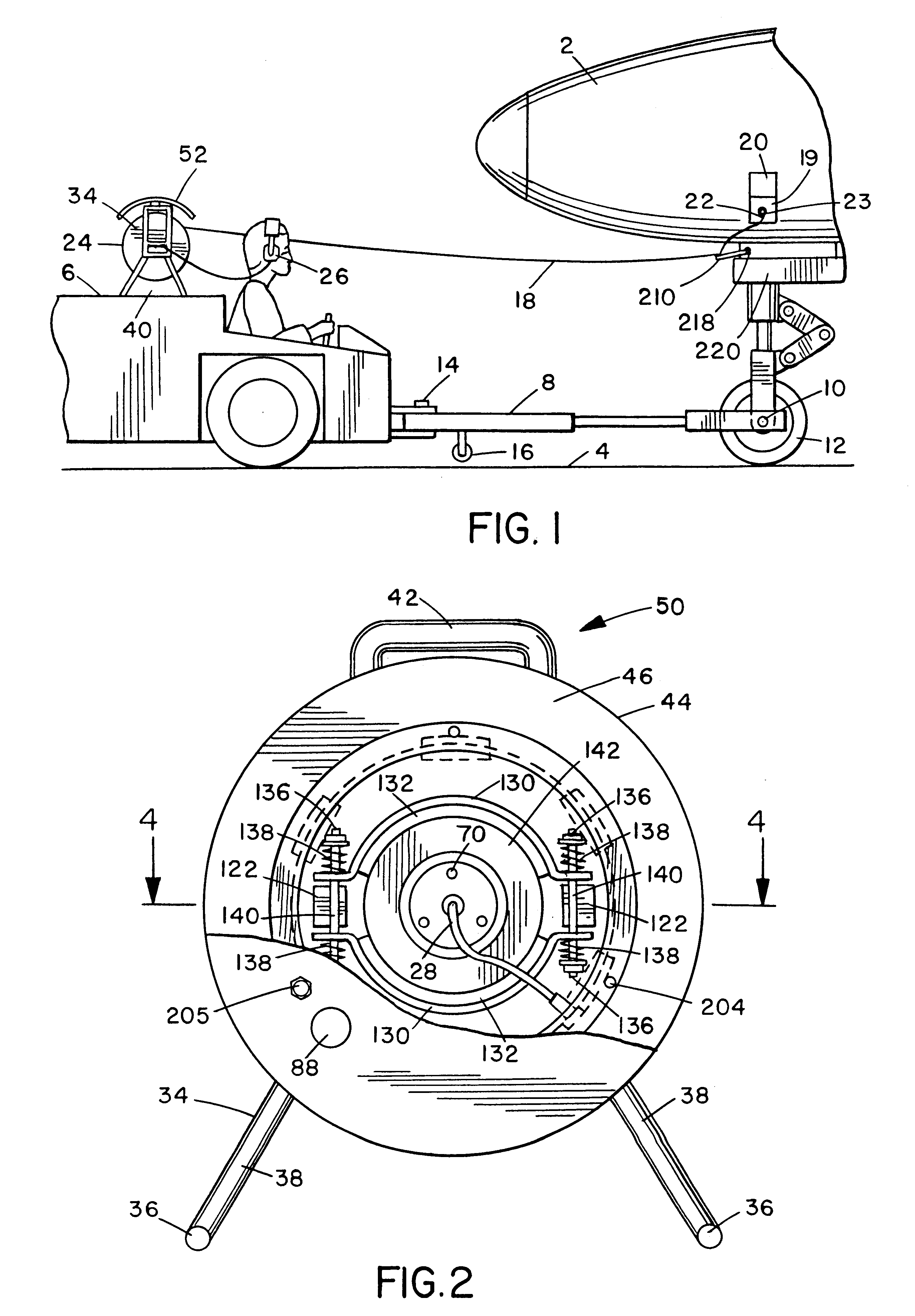
The invention is best understood by reference to the drawings. FIG. 1 illustrates a typical and important end use application of the present invention. (Other potential end use applications will be discussed below.) An aircraft 2 which is on the airport tarmac 4 is connected to an airport tug 6 by a tow / push bar 8. At one end bar 8 is releasably clamped to the hub 10 of the aircraft's nose wheel 12 and at the other end is releasably attached to the tug's tow ball 14 on which it can swivel and rock in a conventional tow / push manner. The tow / push bar also commonly has a dolly wheel 16 which allows it to be moved other than by the tug 6. All of this is conventional.

The cable reel of the present invention is part of the communication system between the tug 6 and the aircraft 2. This system includes a communication cable 18 which at its free end 22 has a plug 21 (FIG. 4) which plugs into a conventional communications jack 23 on the aircraft inside a recess 19 which may be closed by hatch...


PUM


Abstract

A cable reel is disclosed which permits rapid and simple pay out and deployment of cable, retention of cable in operating position, and rapid and controlled retraction of the cable, without overrunning or overwinding of the reel. The reel utilizes a highly functional slip ring capsule which provides positive and continual communications contact and transmission, regardless of adverse weather conditions, handling or operating stresses, or other conditions which would otherwise affect transmissions in prior art devices. It also reduces damage to cables; premature loss of cables through workers' carelessness or deliberate discard of loose cables; operational delays caused by missing cables, or by workers being required to hunt for individual lengths of cable; and delays or malfunctions resulting from having cables of the wrong size, length, weather resistance, etc. A slip-on member prevents damage to the cable tip when the cable is dropped, and a retractable cover prevents damage to the cable tip.

Description

1. Field of the InventionThe invention herein relates to cable reels. More particularly it relates to cable reels which experience severe service and are exposed to harsh weather conditions.2. Description of the Prior ArtAt commercial airports it is common for commercial aircraft to be manoeuvered to and / or away from passenger deplaning / boarding gates or cargo loading facilities by motorized push out / towing vehicles, which are often referred to as airport tugs. As part of such maneuvering, it is necessary for the tug driver and the airplane cockpit crew to be in verbal communication with each other. This is normally done by use of an communication cable running between the tug and the airplane. The cable is plugged into the aircraft's communication system, providing communication between the tug cab and the aircraft's cockpit, each of which includes ear phones and a microphone so that the tug driver and aircraft's pilot can talk to and hear each other.Generally prior art tug-aircraf...

Claims


Application Information

Patent Timeline
Patent Type & Authority Patents(United States)
IPC IPC(8): H02G11/02H02G11/00
CPCH02G11/02
Inventor VAN ESS, QUENTIN W.WALLBAUM, MARK
Owner VAN ESS QUENTIN W
Why Eureka
Try Eureka