Encoder and parameter establishing device therefor

a technology of encoder and parameter, applied in special-purpose recording/indication apparatus, process and machine control, instruments, etc., can solve the problems of increased cost of servo motor and non-functional conventional encoder 45

Inactive Publication Date: 2001-06-05
SANKYO SEIKI MFG CO LTD
View PDF8 Cites 46 Cited by
  • Summary
  • Abstract
  • Description
  • Claims
  • Application Information

AI Technical Summary

Benefits of technology

In accordance with the invention, an encoder comprises position detecting means for detecting a magnetic pole position and a rotational position of a motor. The encoder also includes a memory portion for storing parameter information particular to the motor or the position detecting means. A transmitting portion of the encoder is provided for externally transmitting parameter information particular to the position detecting means as a differential signal. Transmission suspension request detecting means are provided for d

Problems solved by technology

However, conventional encoder 45 does not have a function to determine what kind of encoder shall be used according to kind of the brus

Method used


Image

  • Encoder and parameter establishing device therefor
  • Encoder and parameter establishing device therefor
  • Encoder and parameter establishing device therefor

Examples


example b

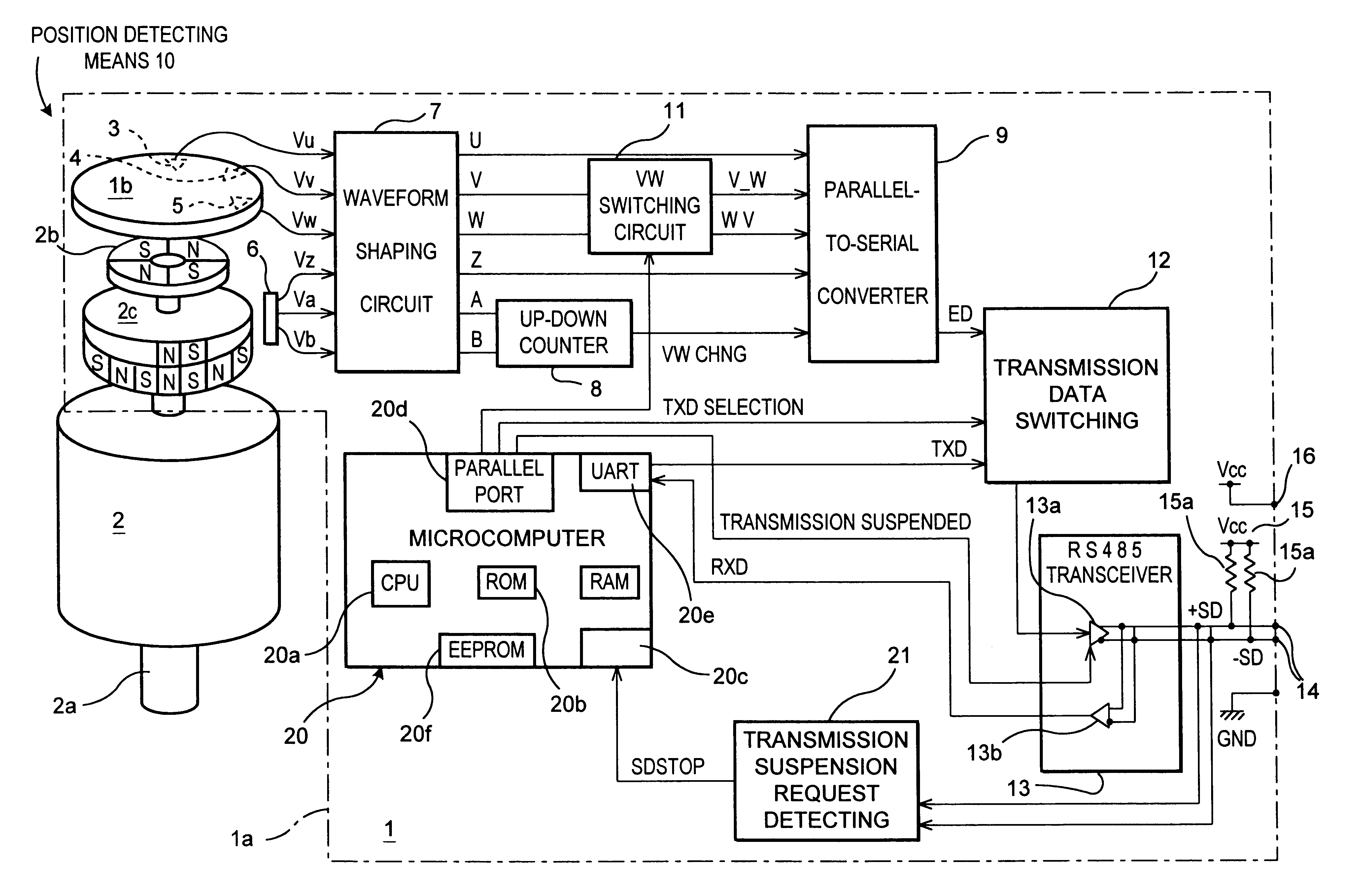
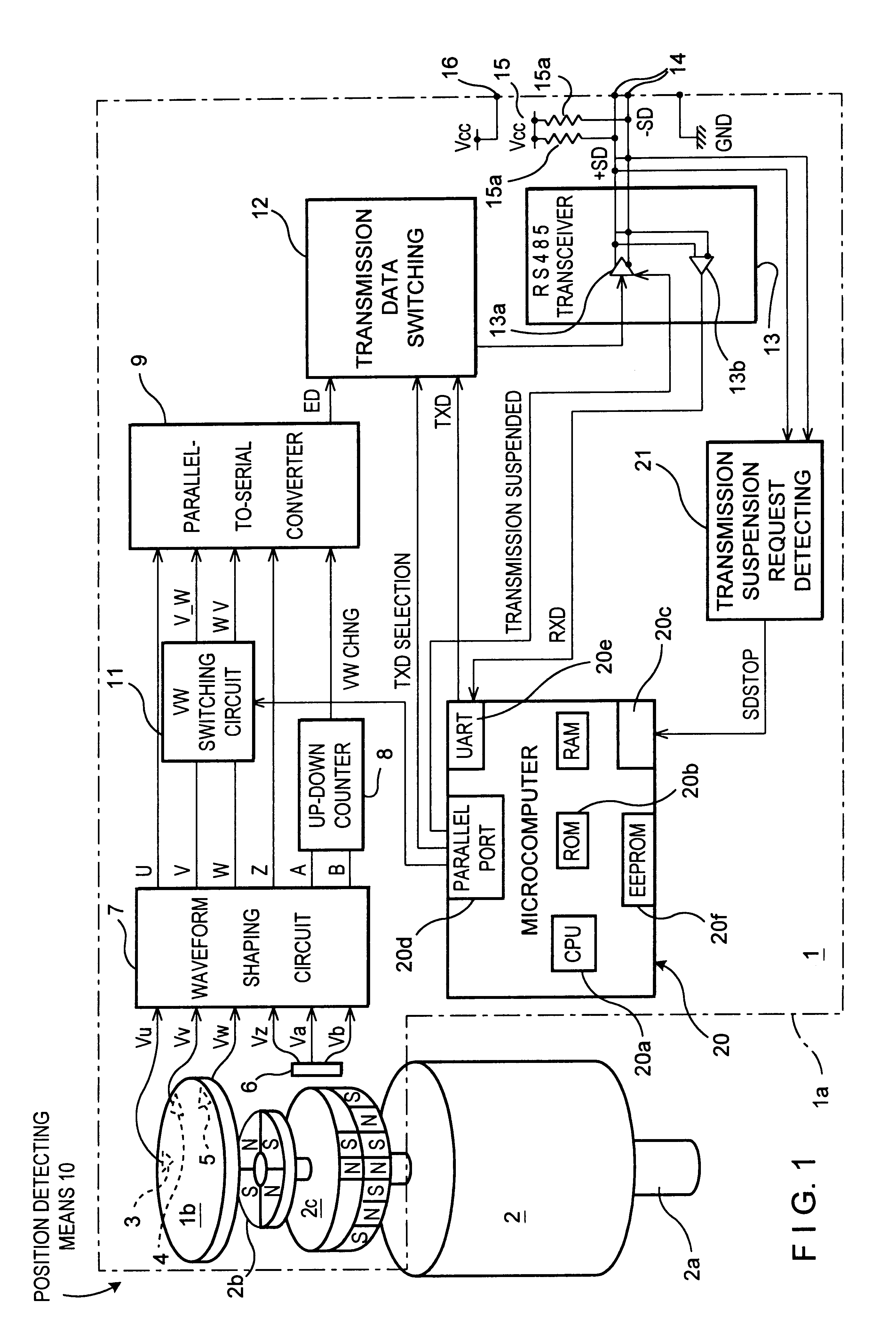
Codes indicating the manufacturing number, model, manufacturer and manufacturing date of the encoder.

example c

Codes assigning a number pulses per rotation in association with A and B phases of the encoder to reestablish the number of pulses; for example, when an older motor having a ratio of pulses per rotation at 1,000 or 500 is replaced with a new motor having a ratio of pulses per rotation at 2,000, the ratio of pulses per rotation in association with the A and B phases in the encoder can be established.

example d

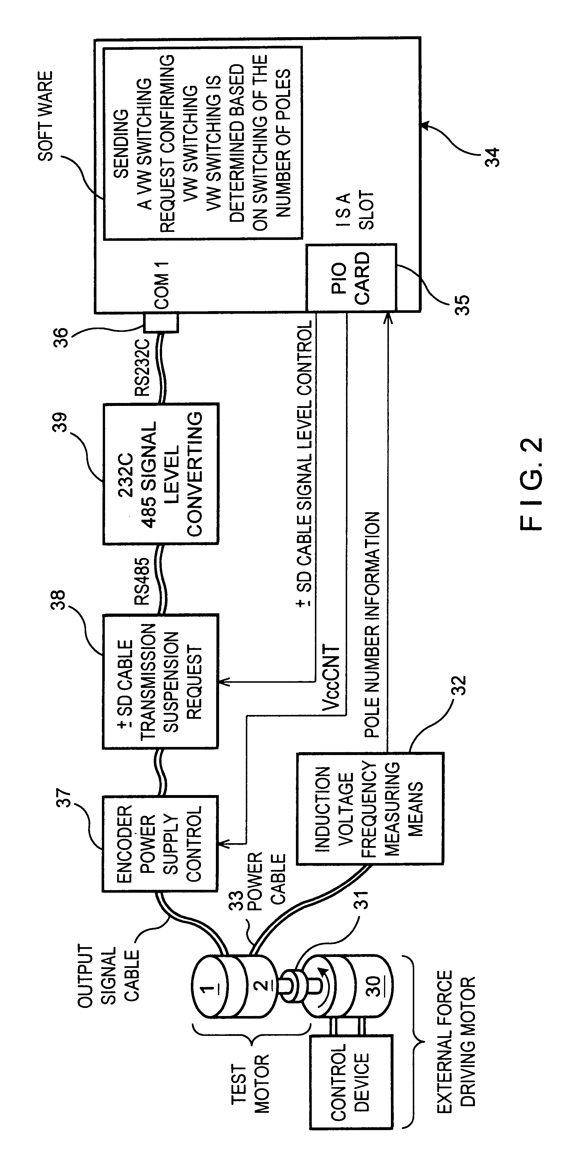
In the case of an output format, in which a plurality of output formats of encoder serial signals are transmitted by the parallel-to-serial converter in the encoder, the format can be assigned. For example, either a serial signal format of encoder maker A or one of encoder maker B can be selected by a personal computer. Furthermore, it is possible to form a plurality of parallel-to-serial converters in which the output thereof is switched.

Also, there is only one channel as an output signal cable in the above embodiment, however, one is not limited to this but the present invention is still applicable even when there is a plurality of output channels.

Moreover, the above embodiment described examples of detecting a condition in which a signal is not recognized as a transmission signal, that is, a condition in which signals from the output signal cables (.+-.SD cables) are at the same level of either high or low. However, it is possible to drive the output signal cables (.+-.SD cables)...


PUM


Abstract

An encoder comprises position detecting device for detecting a magnetic pole position and a rotational position of a motor. The encoder also includes a memory portion for storing parameter information particular to the motor or the position detecting device. A transmitting portion of the encoder is provided for externally transmitting parameter information particular to the position detecting device as a differential signal. A transmission suspension request detecting device is provided for detecting that the differential signal is driven by a given signal externally provided such that the differential signal does not exist as a transmission signal and for generating a transmission suspension request signal requesting suspension of transmission of the differential signal. Finally, a switching control device is provided for switching the transmitting portion to a transmission suspending condition based on the transmission suspension request signal provided by the transmission suspension request detecting device.

Description

a) Field of the Present InventionThe present invention relates to an encoder used for various motors and a parameter establishing device capable of establishing various bits of parameter information for the encoder from the outside of the encoder.b) Description of the Related ArtAs shown in FIG. 8, a conventional servo motor comprises, for example, brushless motor 41, encoder 45, which separately detects data on a rotational position of brushless motor 41 and data on an absolute position of the motor's magnetic poles, and control device 42 which controls the driving of brushless motor 41 according to a detection signal from encoder 45. Also, cables are used for transmission of signals between encoder 45 and control device 42.Encoder 45 is stored in case 50 as shown in FIG. 8 (indicated with a dotted line to avoid making the figure busy) wherein disc-shaped pole detecting magnet 46 is formed at the end of main shaft 41 a of brushless motor 41. Pole detecting magnet 46 transmits drivi...

Claims


Application Information

Patent Timeline
IPC IPC(8): G01D3/02G01D5/245G01D5/00H02K29/08
CPCG01D3/022
Inventor KATAGIRI, TAKASHI
Owner SANKYO SEIKI MFG CO LTD
Why Eureka
Try Eureka