Device for forming a leno selvedge with an electric motor comprising a rotor and a stator accomodating the rotor

a technology of electric motor and rotor, which is applied in the direction of dynamo-electric machines, weaving, looms, etc., can solve the problems of small power density, motor cannot have the required dynamics and power, and the motor must have an extremely high velocity, etc., to achieve the effect of fast inversion of the direction of rotation and high power density

Inactive Publication Date: 2001-06-12
GEBR KLOCKER
View PDF7 Cites 12 Cited by
  • Summary
  • Abstract
  • Description
  • Claims
  • Application Information

AI Technical Summary

Benefits of technology

is therefor to provide a rotary selvedge twisting apparatus of the type mentioned above...

Problems solved by technology

This is a disadvantage since, when using this contrivance as a device for forming a full leno selvedge, the direction of rotation of the rotor must be reversed after a determined number of revolutions in order to undo a twisting of the doup ends on the feeding side of the doup ends.
Since the time available for such an inversion of the direction of rotation is very short due to the high number of weft on modern power-operated looms, the motor must have an extremely high velocity while having a small moment of inertia.
The disadvantage thereof is that the power density that may be achieved with this well-known structural shape of a rotary selvedge twisting apparatus is small.
As a result, the motor cannot have the required dynamics and power that would be necessary to utilize it in a device for forming a leno selvedge since the magnetic flux is not optimal.
This signifies that, in principle just as in the embodimen...

Method used


Image

  • Device for forming a leno selvedge with an electric motor comprising a rotor and a stator accomodating the rotor
  • Device for forming a leno selvedge with an electric motor comprising a rotor and a stator accomodating the rotor
  • Device for forming a leno selvedge with an electric motor comprising a rotor and a stator accomodating the rotor

Examples


Embodiment Construction

)

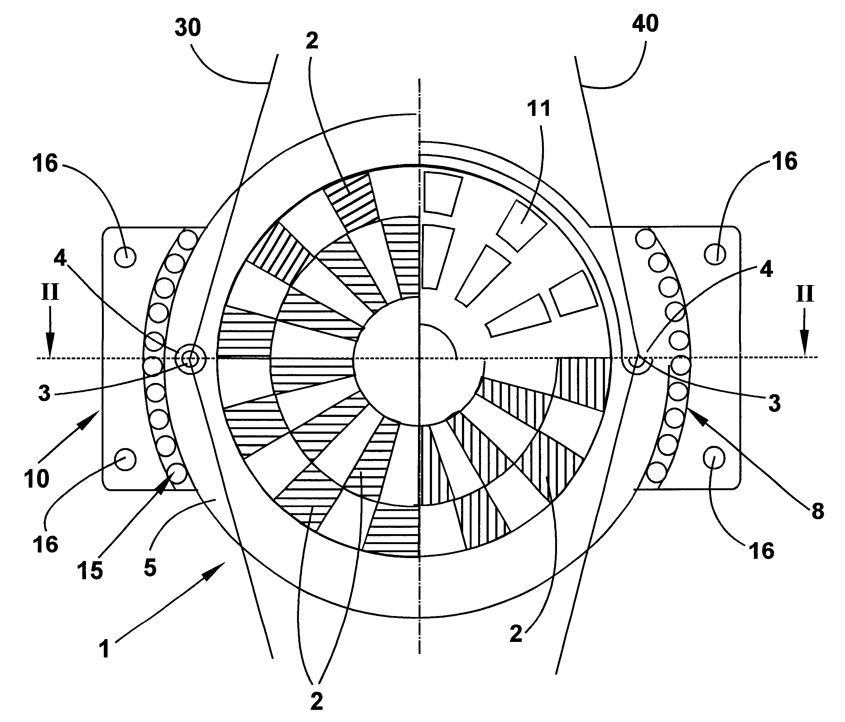
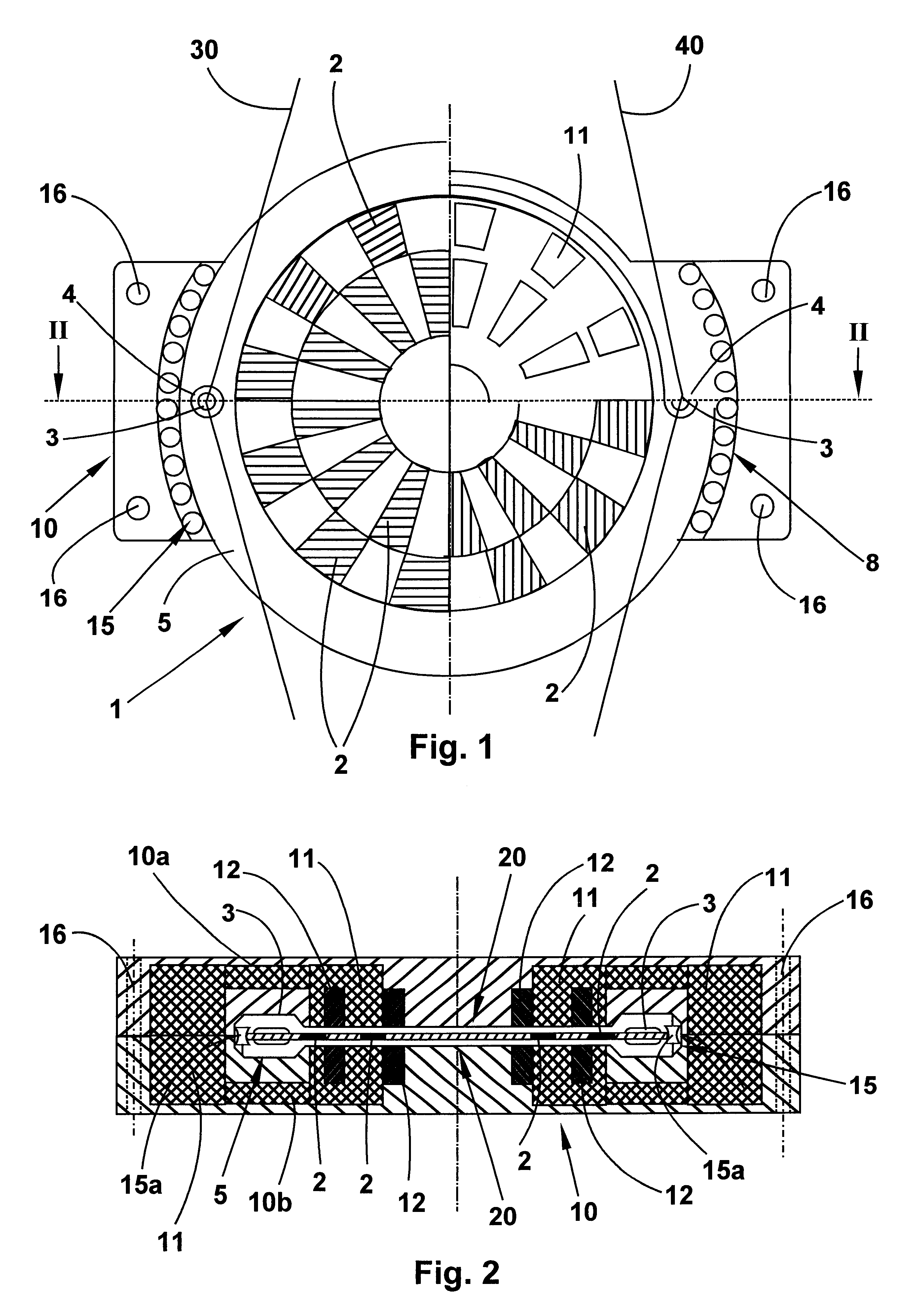
According to the FIGS. 1 and 2, the rotor is referred to with numeral 1 and the stator casing receiving the rotor with numeral 10. The rotor 1 is provided on its surface, on both sides of the rotor, with magnets 2, the magnets 2 on the two sides of the rotor being oppositely poled. This means that the magnet designed as magnetic north on one side of the surface is designed as magnetic south on the other, opposite side of the rotor. The arrangement of the magnets 2 on the rotor is such that two circular arrangements of magnets are created. The rotor itself is additionally provided radially with a ring area 5 that is not equipped with magnets and that is provided with the two apertures 3 through which the doup ends are threaded. To reduce wear, these apertures 3 may be provided with ceramic inserts 4.

The rotor 1 is accommodated in the stator casing 10. The overall stator casing referred to as 10 has C-shaped iron cores 11 with corresponding windings 12, the ends of which being orient...


PUM


Abstract

Device for forming a leno selvedge with an electric motor comprising a rotor (1; 200) and a stator casing (10) accommodating the rotor, whereas the rotor is provided with at least two guiding apertures (3; 216, 216b) for the doup ends and whereas the rotor (1, 200) is provided with several magnetic poles oriented in axial direction, the rotor (1; 200) being provided with two spaced magnetic rings (210, 220) arranged in radial direction, the magnetic rings (210, 220) being provided with several magnet segments (2; 211, 212; 221, 222) each, the magnet segments (2; 211, 212) of the one magnetic ring (2; 210) being locally offset relative to those of the other magnetic ring (2; 210, 220), whereas the rotor (1; 100) is received on both sides in axial direction by the stator casing (10; 225), whereas the stator casing (10; 225) is provided with iron cores (11; 230, 240) with appropriate windings (12; 250), the ends of which being oriented toward the magnetic poles of the rotor.

Description

1. Field of the InventionThe invention relates to a device for forming a leno selvedge with an electric motor comprising a rotor and a stator accommodating the rotor, whereas the rotor is provided with at least two guiding apertures for the doup ends and whereas the rotor is provided with several magnetic poles oriented in axial direction.2. Description of the Prior ArtThe document EP 674 031 discloses a so-called rotary selvedge twisting apparatus for power-operated looms provided with a ring serving as a rotor and lodged in a casing designed as a stator. This ring, which may also be called a disc, has two guiding apertures for threading the doup ends. According to the state of the art, the ring is additionally provided radially, i.e. on its outer periphery, with magnets arranged thereon and cooperating with the corresponding laminations arranged in the stator casing. As the rotor revolves in the casing, the doup ends guided by the rotor in the two thread guiding apertures are twis...

Claims


Application Information

Patent Timeline
IPC IPC(8): D03C7/00D03C7/04D03C7/08H02K7/08H02K7/14H02K21/12H02K21/24D03D47/44
CPCD03C7/04D03C7/08H02K7/088H02K7/14H02K21/24
Inventor HOCKEMEYER, KURTSCHWEMMLEIN, CHRISTOPH
Owner GEBR KLOCKER
Why Eureka
Try Eureka