
Electromagnetic field shielding device

a shielding device and electromagnetic field technology, applied in the direction of discharge tube/lamp details, nuclear engineering, nuclear elements, etc., can solve the problems of device work erroneously, unsuitable for conventional methods, and the effect of user health

Inactive Publication Date: 2001-06-19
PANASONIC CORP
View PDF11 Cites 17 Cited by
  • Summary
  • Abstract
  • Description
  • Claims
  • Application Information

AI Technical Summary

Benefits of technology

The second object of the present invention is to provide a flexible electromagnetic field shielding apparatus which can easily cope with various kinds of electromagnetic fields of different strengths and frequencies.
The third object of the present invention is to provide an electromagnetic field shielding apparatus which can produce a uniform shield effect without changing parts or materials of the apparatus even if the strength or frequency of the electromagnetic field varies over time.
The fourth object of the present invention is to provide an electromagnetic field shielding apparatus which can shield a strong magnetic field over 1.5 tesla.
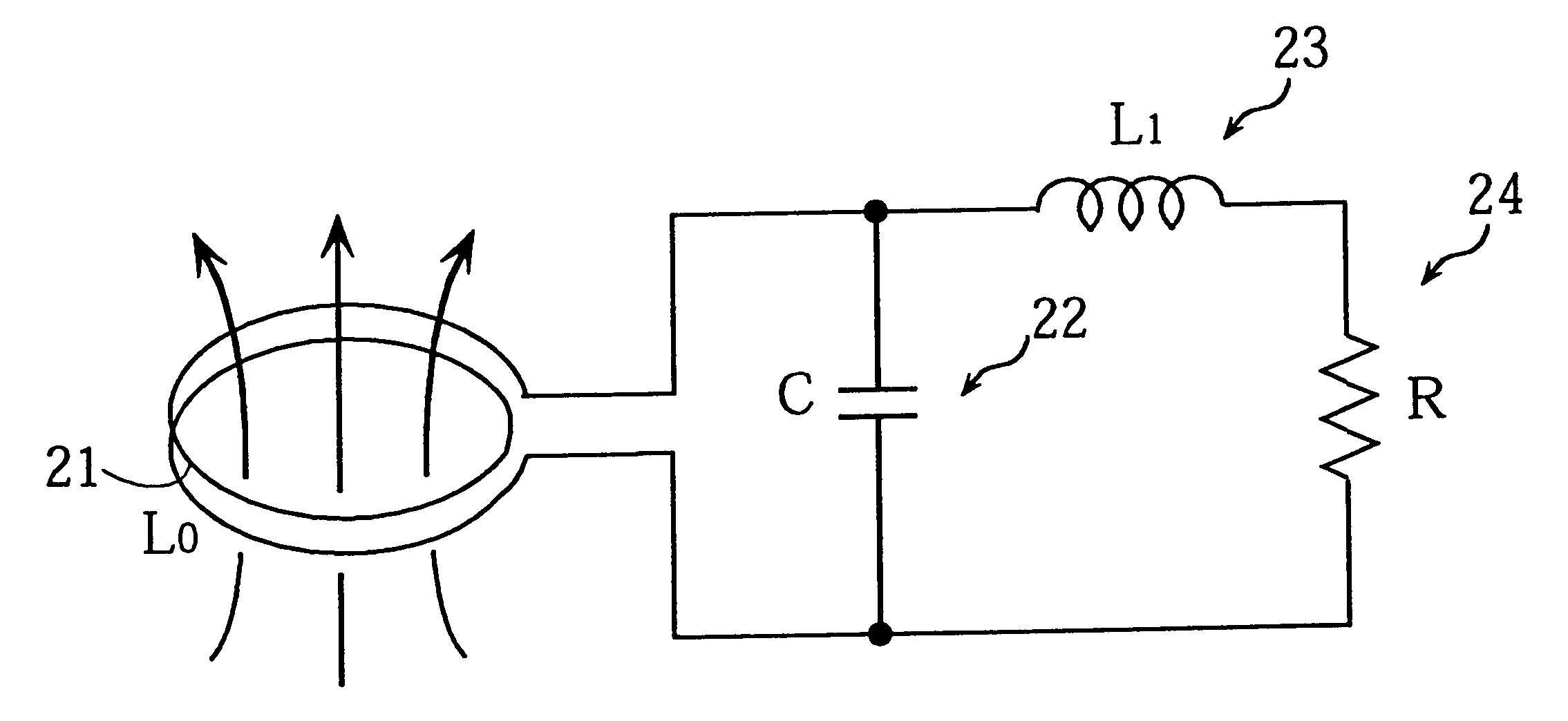
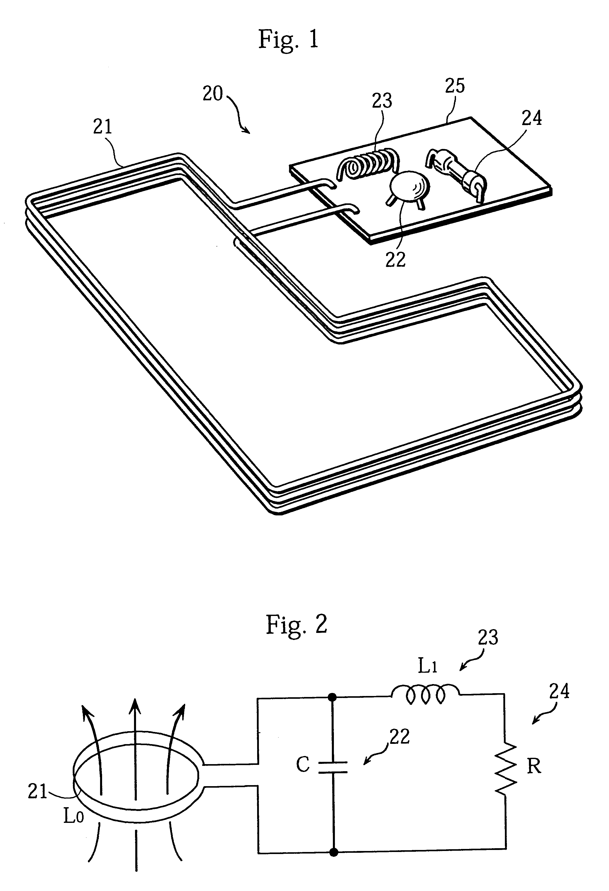
With this apparatus, the electromagnetic field detection means detects an electromagnetic field, an electromotive force is induced in the coil, the electromotive force is supplied to the resonance means, and the energy of the electromotive force is consumed therein. As a result, the strength of the electromagnetic field is suppressed, thereby achieving a shield effect.
With this structure, by changing these circuit parts (the electronic parts or the electric conductor), a resonance means causing a different energy consumption or a resonance means having a different resonance frequency can be obtained without difficulty, thereby achieving the second and fourth objects.
With this structure, the apparatus changes the resonance frequency to follow variation in the frequency or strength of an electromagnetic field, or changes the amount of the energy consumption, thereby achieving the third object.

Problems solved by technology

While weak, such fields can make other devices work erroneously or have adverse effects on the health of users, so that devices need to be shielded.
As described below, however, there are problems with this conventional shield method using the shield member 12.
The first problem is that the opening 11 needs to be covered with a sheet or mesh shield member 12 to produce a high shield effect.
Therefore, if the opening 11 is an opening which something is inserted into or removed from, such as a disk slot of a floppy disk drive, or if the opening is positioned by a moving mechanism, it is not possible to apply these conventional methods as they are.
The second problem is that when various kinds of electromagnetic fields of different strengths or frequencies are generated in a device or when the strength or frequency of an electromagnetic field varies over time, a uniform shield effect cannot be produced with a single shield member 12.
The third problem is that when the shield member 12 is composed of a magnetic material, there will be a limit on the strength of the magnetic field which the shield member 12 can shield.
For instance, it is very difficult for a shield member 12 of a magnetic material to shield a strong magnetic field over 1.5 tesla.

Method used


Image

  • Electromagnetic field shielding device
  • Electromagnetic field shielding device
  • Electromagnetic field shielding device

Examples


Embodiment Construction

in Electrical Device>

The following is a description of examples of the electromagnetic field shielding apparatuses 20, 30, 40, and 50 of Embodiments 1 and 2 and Modifications 1 and 2 applied to an electronic or electrical device.

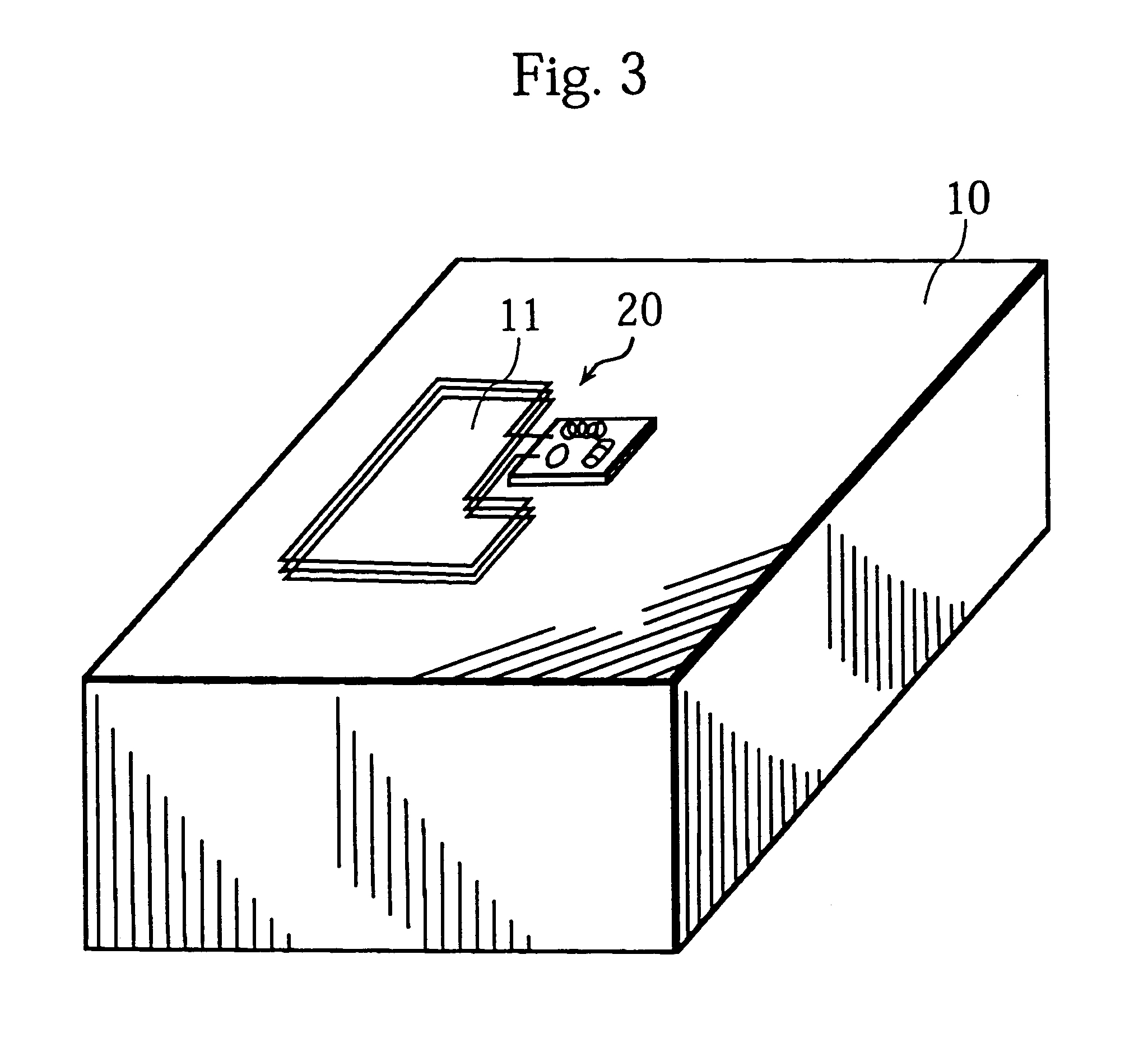
FIG. 18 shows an example of the electromagnetic field shielding apparatus 20 provided on the inside of the front of a CRT device.

With this structure, an unnecessary electromagnetic field, which is generated by the deflecting yoke or high-frequency flyback transformer in a CRT device and emerges from the display screen, is shielded so that user health problems caused by the electromagnetic field can be prevented.

FIGS. 19(a) and 19(b) show an example of the electromagnetic field shielding apparatus 20 provided on the inside of the front of a mobile phone.

With this structure, an unnecessary electromagnetic field radiated forward from a PLL synthesizer or transmission amplifier in the cellular phone is suppressed, reducing the influence of such fields on the hea...


PUM


Abstract

The electromagnetic field shielding apparatus of the present invention includes the electromagnetic field detection coil 21 for detecting an AC leakage electromagnetic field and the parallel resonance circuit 22-24 whose circuit constants are predetermined so that the resonance frequency matches the frequency of the electromotive force induced by the electromagnetic field detection coil 21. The resistor 24 of the parallel resonance circuit 22-24 consumes energy so that the strengths of the magnetic and electrical fields passing through the electromagnetic field detection coil 21 are suppressed.

Description

The present invention relates to an apparatus which shields an electromagnetic field emerging from the inside of an electrical device, and in particular to a resonance-type shield and an active shield which both use electronic circuitry.DESCRIPTION OF THE PRIOR ARTElectrical and electronic devices can generate electromagnetic fields. While weak, such fields can make other devices work erroneously or have adverse effects on the health of users, so that devices need to be shielded.Shield members made of electric conductors or ferromagnetic materials are conventionally used to shield the electromagnetic fields (see Journal of the Electrical Society Vol. 116, April 1996, p203-p217).FIGS. 21(a) and 21(b) are drawings that show a conventional method for shielding an electromagnetic field with a shield member.FIG. 21(a) shows a state where an electromagnetic field generated in an electrical device is emerging from the opening 11 of the chassis 10.FIG. 21(b) shows a state where the opening ...

Claims


Application Information

Patent Timeline
Patent Type & Authority Patents(United States)
IPC IPC(8): G01R1/02G01R1/18G01R29/08H01J29/00H01Q1/52H01Q1/00H04B15/00H04N5/645
CPCG01R1/18G01R29/0814H01J29/003H01Q1/526H04B15/00G01R29/0878H01J2229/0023H04N5/645
Inventor SAKIYAMA, KAZUYUKI
Owner PANASONIC CORP
Learn More