Surface micro-machined acoustic transducers

a micro-machined acoustic transducer and surface technology, applied in piezoelectric/electrostrictive transducers, force measurement using piezo-resistive materials, generators/motors, etc., can solve the problems of depth of acoustic cavity and undesirable frequency over 500 hz

Inactive Publication Date: 2001-06-19
LUCENT TECH INC +1
View PDF15 Cites 62 Cited by
  • Summary
  • Abstract
  • Description
  • Claims
  • Application Information

AI Technical Summary

Problems solved by technology

One problem with some micro-machined transducers is related to the depth of the acoustic cavity 7.
Frequencies greater than about 500 Hz are undesirable because such frequencies are large enough to break the hinges connecting enclosure sides with one another.

Method used


Image

  • Surface micro-machined acoustic transducers
  • Surface micro-machined acoustic transducers
  • Surface micro-machined acoustic transducers

Examples


Embodiment Construction

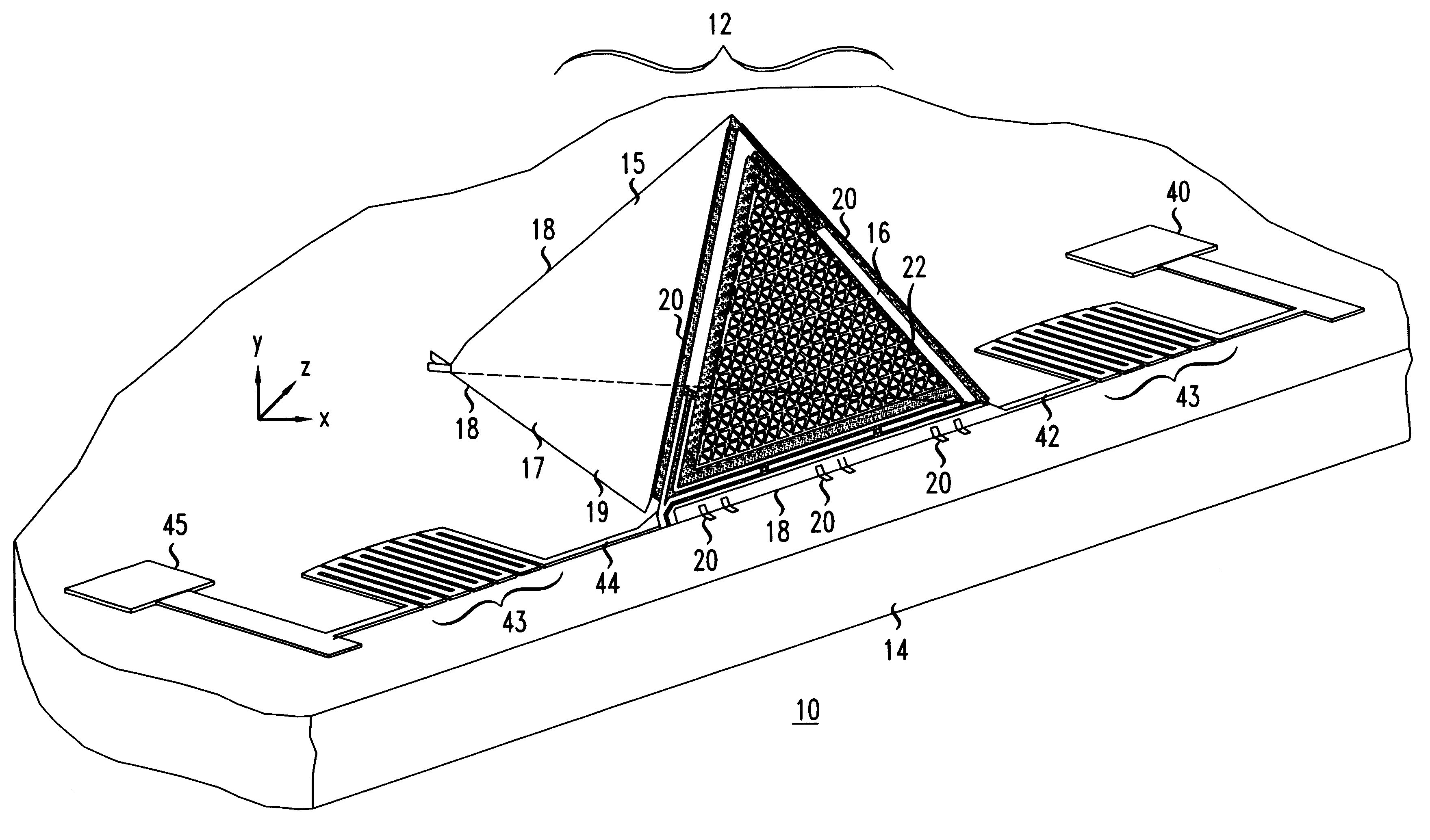
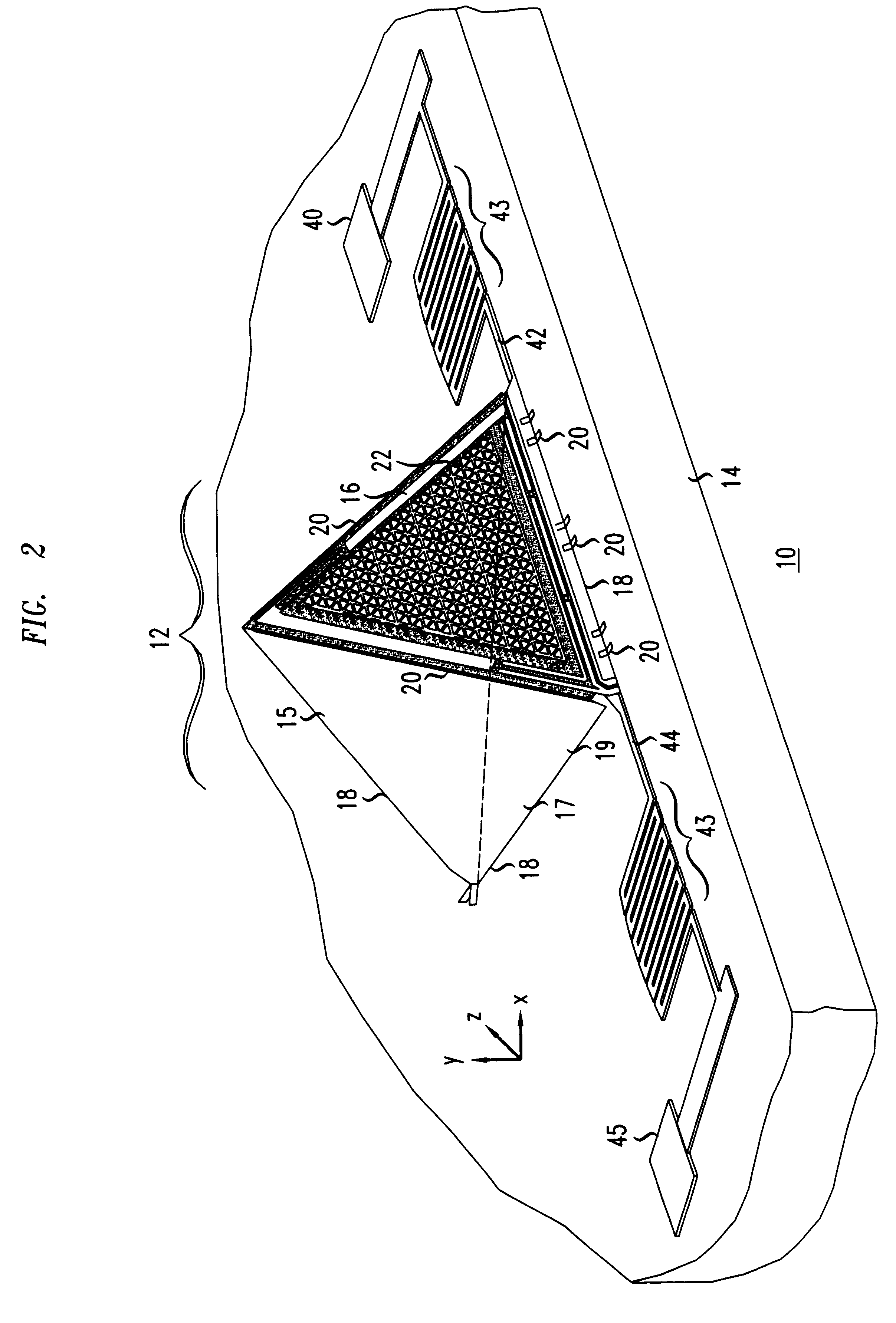
An acoustic enclosure having the tetrahedral shape depicted in FIG. 2 was formed. The acoustic enclosure was formed on a surface of a silicon substrate. The silicon substrate had a 2 .mu.m (micrometers) thick silicon dioxide sacrificial layer over a 600 nm (nanometer) thick silicon nitride layer formed thereon.

A 2 .mu.m polysilicon layer having a tensile strength of about 3 Mpa was formed on the silicon dioxide sacrificial layer. Three triangular enclosure sides 15, 16, 17 attached one to another with hinges 20, as illustrated in FIG. 5, were defined in the polysilicon layer. The edges of each enclosure side 15, 16, 17 had a length of about 650 .mu.m (micrometers).

After the enclosure sides 15, 16, 17 were defined in the 2 .mu.m thick polysilicon layer, enclosure side 16 was configured to receive acoustic energy in triangular region 22. First, an acoustic membrane was defined in a region of the 2 .mu.m thick polysilicon enclosure side 16. Thereafter, an 800 nm thick silicon dioxide s...


PUM

PropertyMeasurementUnit
frequencyaaaaaaaaaa
anglesaaaaaaaaaa
frequenciesaaaaaaaaaa

Abstract

A micro-machined transducer having a structure in which an acoustic enclosure is formed on a substrate above the plane of the substrate surface is disclosed. Forming the acoustic enclosure on the substrate above the plane of the substrate surface, rather than an acoustic cavity in a surface of the substrate, provides an acoustic cavity whose size is not limited by the thickness of the substrate.

Description

The present invention relates to acoustic transducers and more specifically to, micro-machined acoustic transducers.DESCRIPTION OF THE RELATED ARTTransducers are devices which convert input energy in one form into output energy in another form. For example, microphones are acoustic transducers that convert input acoustic energy into output electrical energy. Micro-machined acoustic transducers are miniature transducers (sub-centimeter in size) fabricated with techniques commonly used for making integrated circuits (e. g., material deposition / growth, lithography, and etching). Potential uses for micro-machined acoustic transducers include microphones for hearing aids and pressure sensors for automobiles. Scheeper, P. R., et al. "A Review of Silicon Microphones", Sensors and Actuators, Vol. A 44 (1994) pp. 1-11, describes several micro-machined transducers suitable for converting acoustic signals into electrical signals. A cross-sectional view of one such micro-machined acoustic trans...

Claims


Application Information

Patent Timeline
Patent Type & Authority Patents(United States)
IPC IPC(8): H04R19/00
CPCH04R19/00Y10T29/42
Inventor BISHOP, DAVID JOHNBOIE, ROBERT ALBERTPARDO, FLAVIO
Owner LUCENT TECH INC
Why Eureka
Try Eureka