Heat exchanging roll

a technology of heat exchanger and roll, which is applied in the direction of heat exchangers, moving conduit heat exchangers, lighting and heating apparatus, etc., can solve the problem of only operating with certain temperature differentials

Inactive Publication Date: 2001-06-26
VOITH PATENT GMBH
View PDF13 Cites 15 Cited by
  • Summary
  • Abstract
  • Description
  • Claims
  • Application Information

AI Technical Summary

Benefits of technology

Preferably, the pump mechanism is mounted on the roll and rotates therewith. Accordingly, no moving connections are necessary in the path of the internal heat transfer fluid, with a corresponding reduced chance of leaks. Mounting the pump mechanism is also simplified, as movable mounts are unnecessary.
Also in the exemplary embodiment, the pump mechanism surrounds a roll journal in a ring shape. This uniformly distributes the weight of the pump mechanism around the circumference of the roll, minimizing any imbalance.
In an exemplary embodiment, the pump mechanism arrangement has at least one pump disposed as far from the radial center of the roll as possible. The pump will thus not have to overcome centrifugal force to circulate the internal heating transfer fluid. In most cases, centrifugal force will return the internal heat transfer fluid to the pump. In any case, with this design, the internal heat transfer fluid is always present at the pump intake.
Preferably, the external heat transfer fluid is fed centrally to the heat exchanger, and the outflow takes place radially farther out. This has the advantage that centrifugal force provides at least part of the energy needed to circulate the fluid.
In an exemplary embodiment, the secondary side of the heat changer has a plurality of tubes in parallel with an axis of the roll, disposed in a heat exchanger chamber and which connect with a feed connection. This provides a relatively large surface for the heat transfer from the external to the internal heat transfer fluid, or vice versa. With a heated roll, the arrangement has the advantage that steam (the preferable external heat transfer fluid) condenses on the outside of the tubes to deliver heat to the internal heat transfer fluid flowing through the tubes. Because of the rotation of the roll, any condensate is immediately thrown off the tubes, such that it does not interfere with the heat transfer. Consequently, the heat transfer surfaces are "self-cleaning."

Problems solved by technology

A drawback of such a heat exchanger is that it operates only with certain temperature differentials, and only for cooling the roll.

Method used


Image

  • Heat exchanging roll
  • Heat exchanging roll
  • Heat exchanging roll

Examples


Embodiment Construction

The particulars shown herein are by way of example and for purposes of illustrative discussion of the exemplary embodiments of the present invention only, and represents in the cause of providing what is believed to be the most useful and readily understood description of the principles and conceptual aspects of the invention. In this regard, no attempt is made to show structural details of the invention in more detail than necessary for the fundamental understanding of the invention, the description taken with the drawings making apparent to those skilled in the art how the several forms of the invention may be embodied in practice.

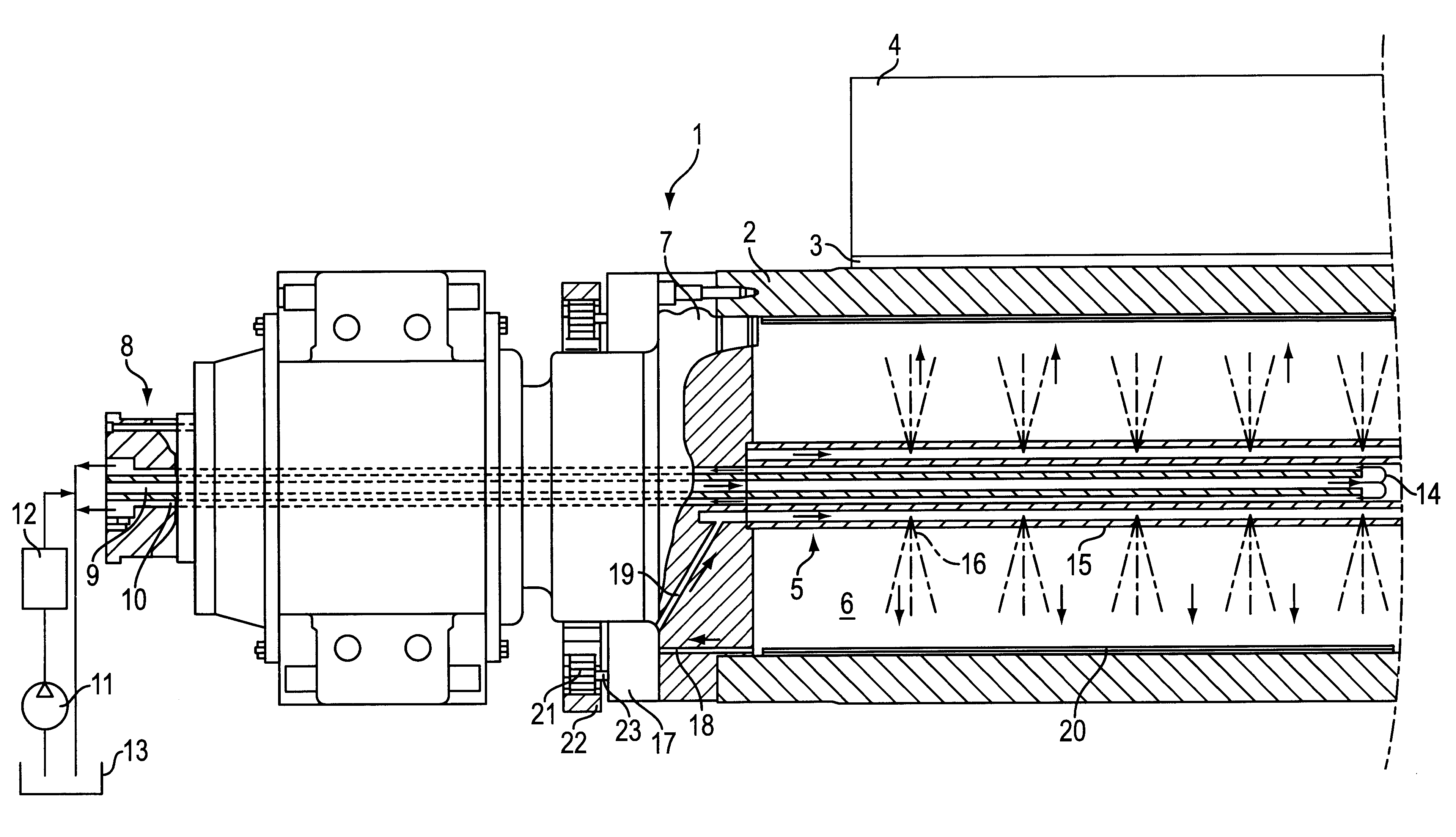
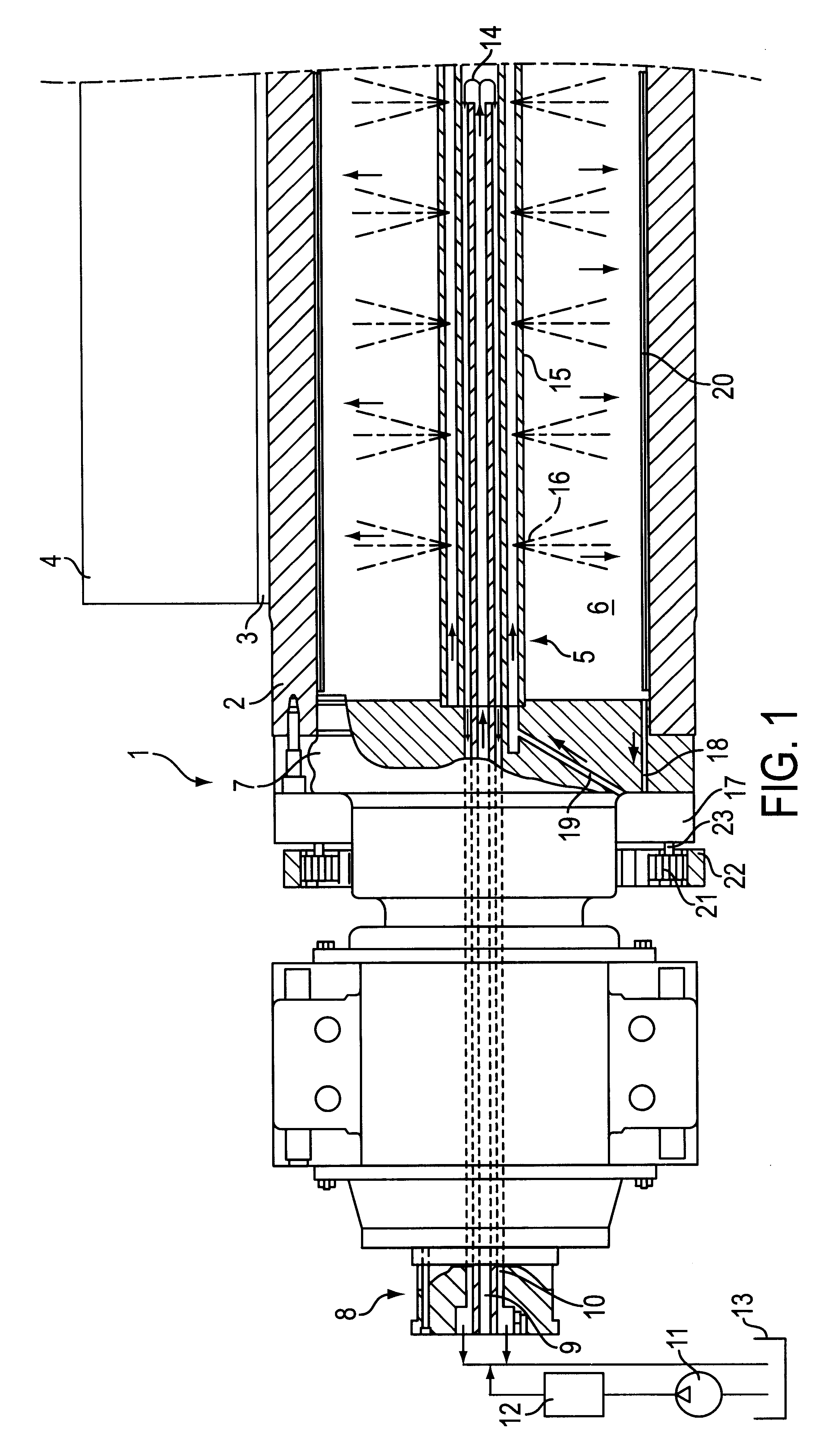
Referring now to FIG. 1, the left end of a roll 1, preferably a cooling roll, is shown. Roll 1 has a roll jacket 2 with an elastic coating 3. Roll 1 cooperates with an opposing roll 4 to process a material web (not shown). Over time, coating 3 is periodically fulled and builds up heat which must be dissipated.

A heat exchanger 5 is centrally disposed in t...


PUM


Abstract

A heat exchange roll. The roll includes a roll jacket, and a heat exchanger mounted inside the roll jacket. A supply mechanism controls an inflow and outflow of an external heat transfer fluid to a primary side of the heat exchanger. An internal heat transfer fluid has a fluid path between an inner portion of the roll jacket and a secondary side of the heat exchanger. A pump mechanism pumps the internal heat transfer fluid over the fluid path.

Description

The present application claims priority under 35 U.S.C. .sctn. 119 of German Patent Application No. 198 14 597.7, filed Apr. 1, 1998, the disclosure of which is expressly incorporated by reference herein in its entirety.1. Field of the InventionThe present invention is directed to a roll with a heat exchanger. More specifically, the present invention is directed to a roll having a heat exchanger disposed inside the roll jacket. The heat exchanger connects with a supply mechanism for inflow and outflow of an external heat transfer fluid to its primary side. A secondary side of the heat exchanger and an inner surface of the roll jacket support an internal heat transfer fluid.2. Discussion of the Background InformationDD 225 767 A1 discloses rolls used in calenders to process paper webs or other material webs. Rolls cooperate with adjacent rolls to form nips therebetween. It is known in such arrangements that it is often preferable to heat or cool the material web, either at a nip or a...

Claims


Application Information

Patent Timeline
Patent Type & Authority Patents(United States)
IPC IPC(8): D21F5/10D21F5/00D21G1/02D21G1/00D21F5/02
CPCD21F5/028D21F5/10D21G1/0266
Inventor HENDRIX, GOTTFRIED
Owner VOITH PATENT GMBH
Why Eureka
Try Eureka