This helps you quickly interpret patents by identifying the three key elements:
Problems solved by technology
Method used
Benefits of technology
Problems solved by technology
Accordingly, when for example, in an attempt to drive the ultrasonic motor at the resonance frequency, the frequency of the high frequency voltages are variously varied to effect the retrieval of the resonance frequency, there is the possibility that in some cases, the frequency may be dropped too much and the ultrasonic motor may become unable to be started.
However, in the aforedescribed prior-art ultrasonic actuator, it has been difficult to yield shape accuracy when the piezoelectric elements for torsional vibration are combined into an annular shape.
Therefore, the areas of the piezoelectric elements have become smaller and it has been difficult to obtain high torque and high-speed rotation of the motor.
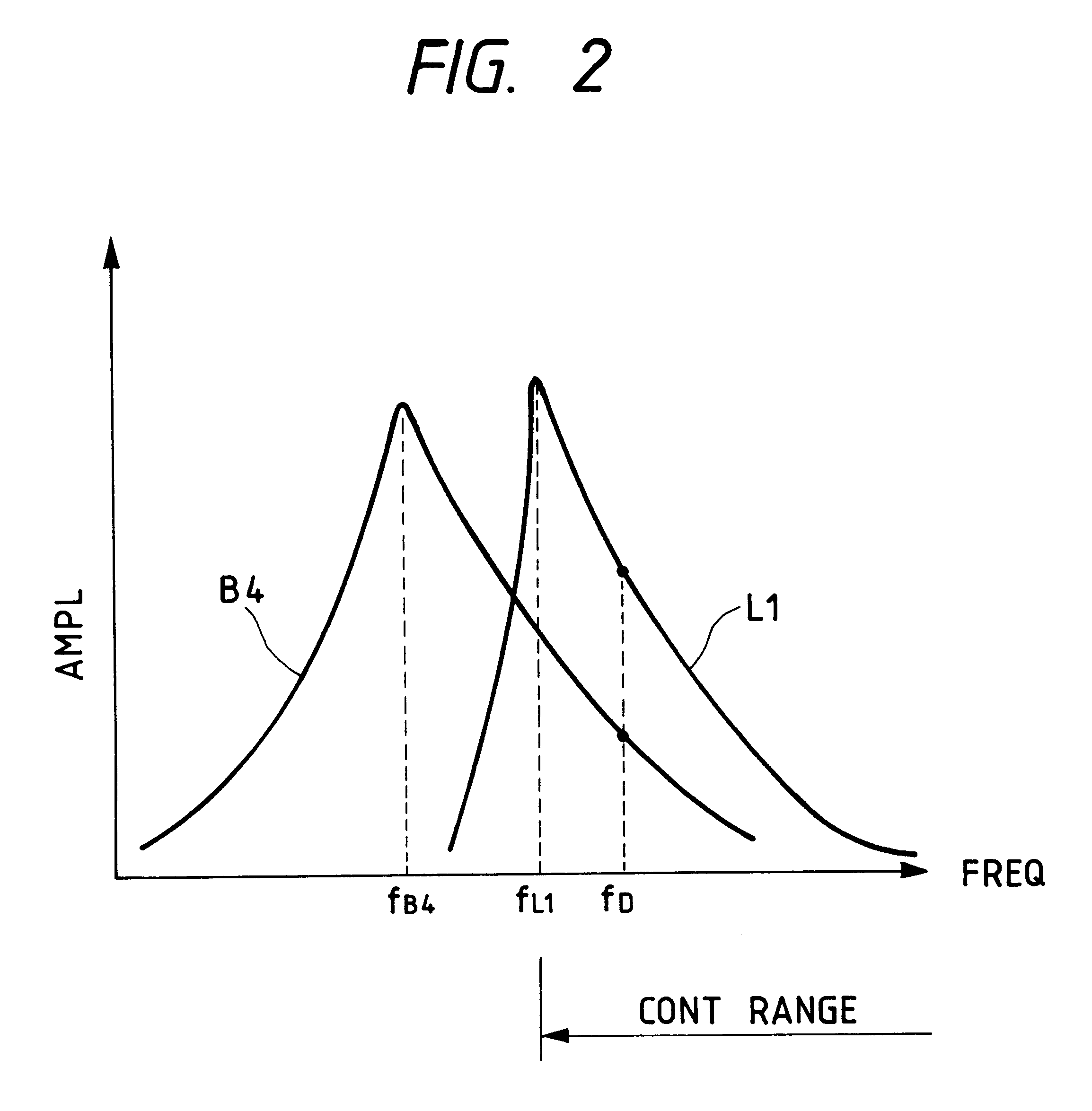
This ultrasonic actuator can be stably driven at a frequency higher than the resonance frequency, but the stable driving thereof is difficult at a frequency lower than the resonance frequency.
This has led to the problem that rotational motion becomes unstable and along therewith, the drive force and driving efficiency are reduced.
Accordingly, the prior-art ultrasonic actuator has suffered from the problem that depending on the manufacture thereof, there is a case where stable driving is obtained and there is a case where stable driving is not obtained, and this gives birth to an individual difference in performance.
However, when the resonance frequency of the bending vibration is higher than the resonance frequency of the longitudinal vibration, the frequency of the high frequency voltages applied to the piezoelectric elements 11 and 12 may sometimes become equal to or lower than the resonance frequency of the bending vibration even if it is equal to or greater than the resonance frequency of the longitudinal vibration, and in such case, there is the possibility that bending vibration is not created.
Method used
Image
Click on the blue label to locate the original text in one second.
Reading with bidirectional positioning of images and text.
By thus adjusting the length of the mover in the lengthwise direction thereof, the resonance frequency of torsional vibration could be made higher than the resonance frequency of longitudinal vibration.
The operation of the ultrasonic actuator of this embodiment will now be described.
The oscillating portion 121 oscillates to produce a driver signal, which is divided into two signals having a phase difference of (1 / 4).lambda. by the phase shifting portion 122, and the two signals are amplified by the T-amplifying portion 123 and the L-amplifying portion 124, respectively.
The driving signal amplified by the T-amplifying portion 123 is inputted to the piezoelectric member 104 for torsional vibration, and the driving signal amplified by the L-amplifying portion 124 is inputted to the piezoelectric...
second embodiment
An attempt has been actually made to design an ultrasonic actuator using a heteromorphic mode degeneration type vibrator of longitudinal vibration and torsional vibration according to a The stator 151 is formed of two kinds of materials, i.e., resilient members 152, 153 and piezoelectric members 154, 155 and further, the resilient members 152, 153 are of a complicated shape so as to have large-diametered portions and small-diametered portions. Here, in order to improve the accuracy of calculation, the resonance frequencies of torsional vibration and longitudinal vibration have been found by the finite element method.
Resilient members 152, 153: stainless steel
Piezoelectric member 154 for torsional vibration: PZT of thickness 0.5 mm d.sub.15 =510.times.10.sup.-12 m / V
Piezoelectric member 155 for
longitudinal vibration: PZT of thickness 0.5 mm d.sub.31 =-135.times.10.sup.-12 m / V
example 3
of the Manufacture
Length of the first large-diametered portions: 20 mm
Length of the small-diametered portions: 1 mm
Length of the second large-diametered portions: 4 mm
Resonance frequency of longitudinal vibration: 72.9 kHz
Resonance frequency of torsional vibration: 73.4 kHz
PUM
Abstract
An ultrasonic motor includes a vibrator vibrating in conformity with a frequency voltage. A relative motion member effects relative vibration in conformity with the vibration of the vibrator. The vibrator is adapted to vibrate in a first vibration mode and a second vibration mode vibrating in a direction differing from the first vibration mode. The resonance frequency of the first vibration mode is higher than the resonance frequency of the second vibration mode.
Description
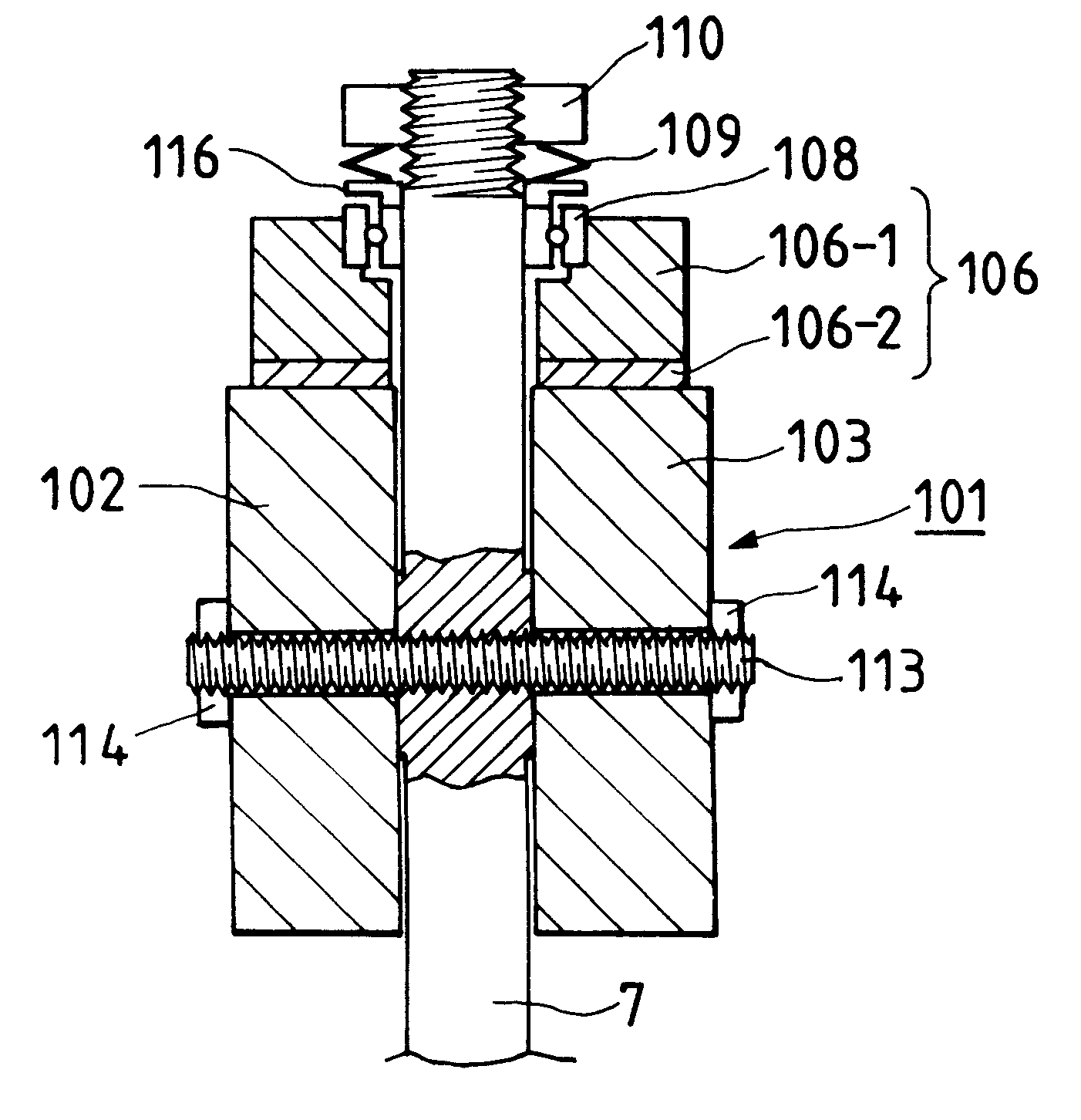
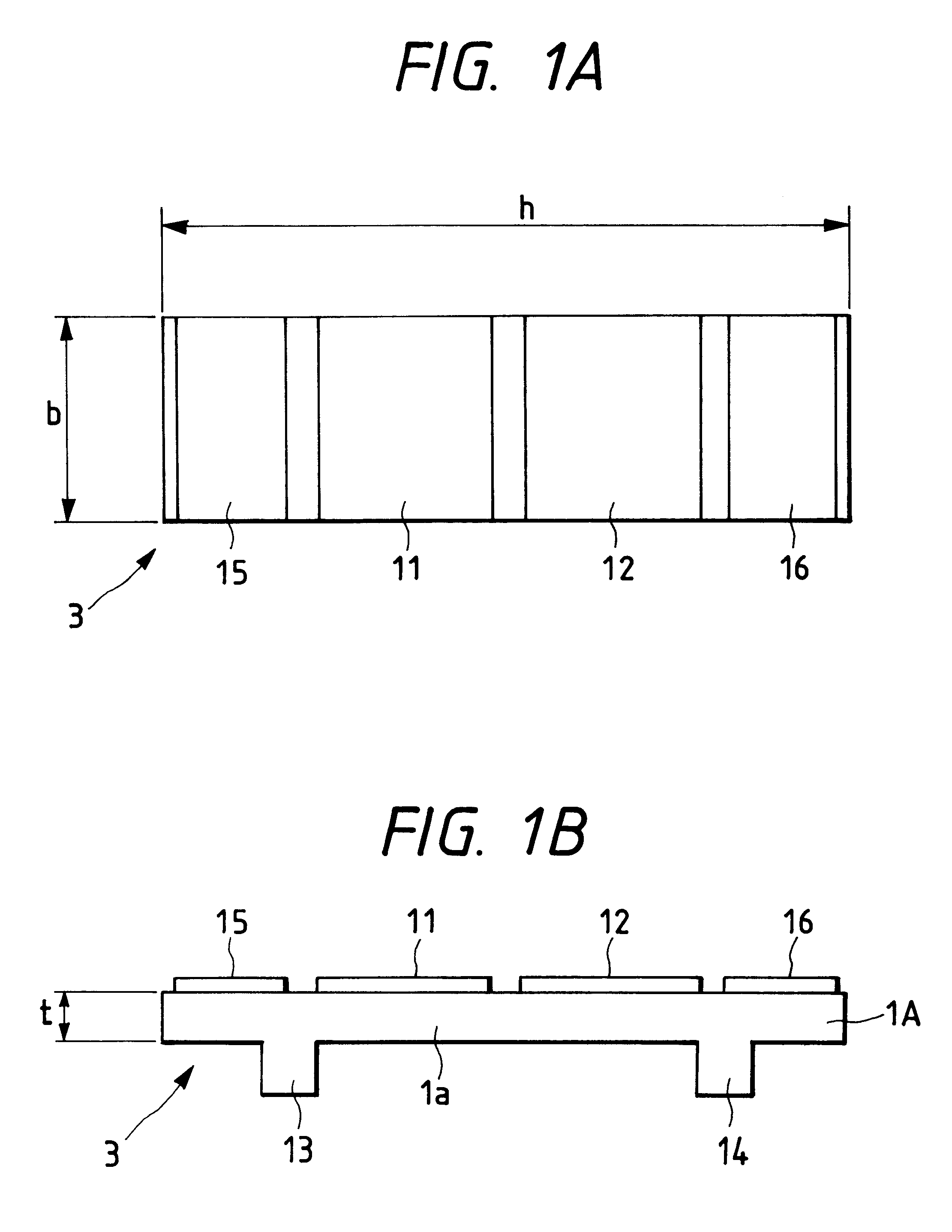
1. Field of the InventionThis invention relates to an ultrasonic motor utilizing ultrasonic vibration and an ultrasonic actuator.As an ultrasonic motor of this kind, there is known a "heteromorphic degeneration longitude L1-bend B4 mode planar motor" described, for example, in "the Lecture Papers in the 5th Dynamics Symposium Related to Electromagnetic Force".FIGS. 4A to 4C of the accompanying drawings show the structure of the ultrasonic motor described in the above-mentioned publication. FIG. 4A is a view of the ultrasonic motor as it is seen from just above it, FIG. 4B is a cross-sectional view of the ultrasonic motor taken in the direction of arrow P, and FIG. 4C is a cross-sectional view of the ultrasonic motor taken in the direction of arrow Q.In FIGS. 4A to 4C, the reference numeral 1 designates a resilient member having piezoelectric elements 11 and 12 adhesively secured to the upper surface thereof, and electrodes, not shown, are adhesively secured to the upper surfaces of ...
Claims
Application Information
Patent Timeline
Application Date:The date an application was filed.
Publication Date:The date a patent or application was officially published.
First Publication Date:The earliest publication date of a patent with the same application number.
Issue Date:Publication date of the patent grant document.
PCT Entry Date:The Entry date of PCT National Phase.
Estimated Expiry Date:The statutory expiry date of a patent right according to the Patent Law, and it is the longest term of protection that the patent right can achieve without the termination of the patent right due to other reasons(Term extension factor has been taken into account ).
Invalid Date:Actual expiry date is based on effective date or publication date of legal transaction data of invalid patent.

