Ultrasonic motor and ultrasonic vibrator

a technology of ultrasonic motor and ultrasonic vibrator, which is applied in piezoelectric/electrostrictive/magnetostrictive devices, piezoelectric/electrostriction/magnetostriction machines, electrical apparatus, etc., can solve the problems of deterioration of ultrasonic motor performance, poor shock resistance, and complicating work, so as to achieve high shock resistance and high efficiency.

Inactive Publication Date: 2009-10-15
SHARP KK
View PDF0 Cites 29 Cited by
  • Summary
  • Abstract
  • Description
  • Claims
  • Application Information

AI Technical Summary

Benefits of technology

[0012]The invention has been made in view of the above problems, and an object of the invention is to provide an ultrasonic motor that has high resistances to shock and wear, and can operate with high efficiency.

Problems solved by technology

The piezoelectric element used in the ultrasonic vibrator is formed of a brittle material such as ceramic so that it has a poor shock resistance.
It has been known that wear due to driving occurs in contact portions of the ultrasonic vibrator and an external driver such as a rotor, resulting in deterioration of performance of the ultrasonic motor.
According to the above structures, however, each of contact portion 907 and vibration plate 905 has the arc-shaped portion and the linear portion in a mixed fashion, which complicates working thereof.
This space prevents efficient transmission of the vibration of vibration plate 905 to contact portion 907, resulting in loss of an output power of the ultrasonic vibrator.

Method used


Image

  • Ultrasonic motor and ultrasonic vibrator
  • Ultrasonic motor and ultrasonic vibrator
  • Ultrasonic motor and ultrasonic vibrator

Examples


first embodiment

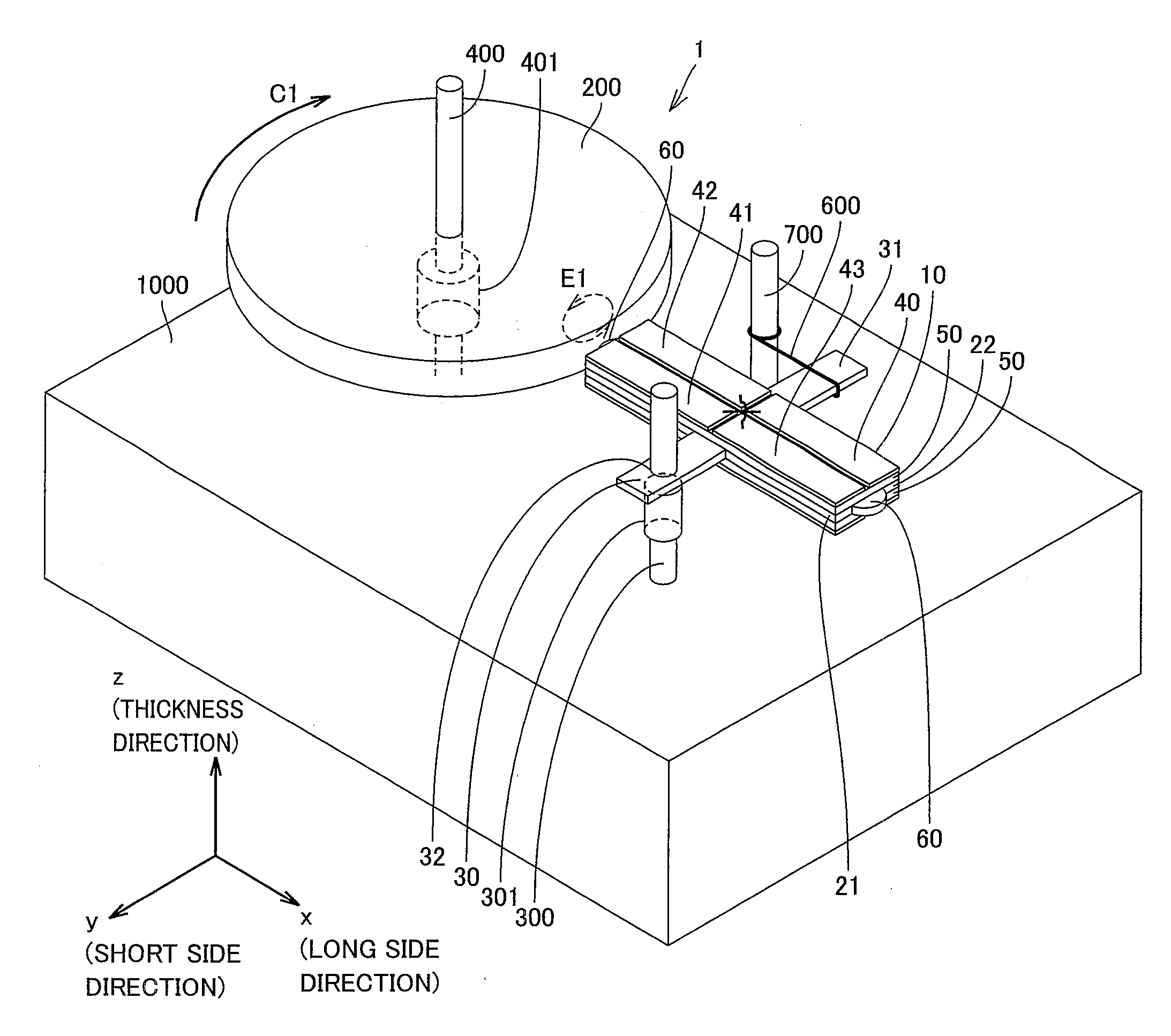
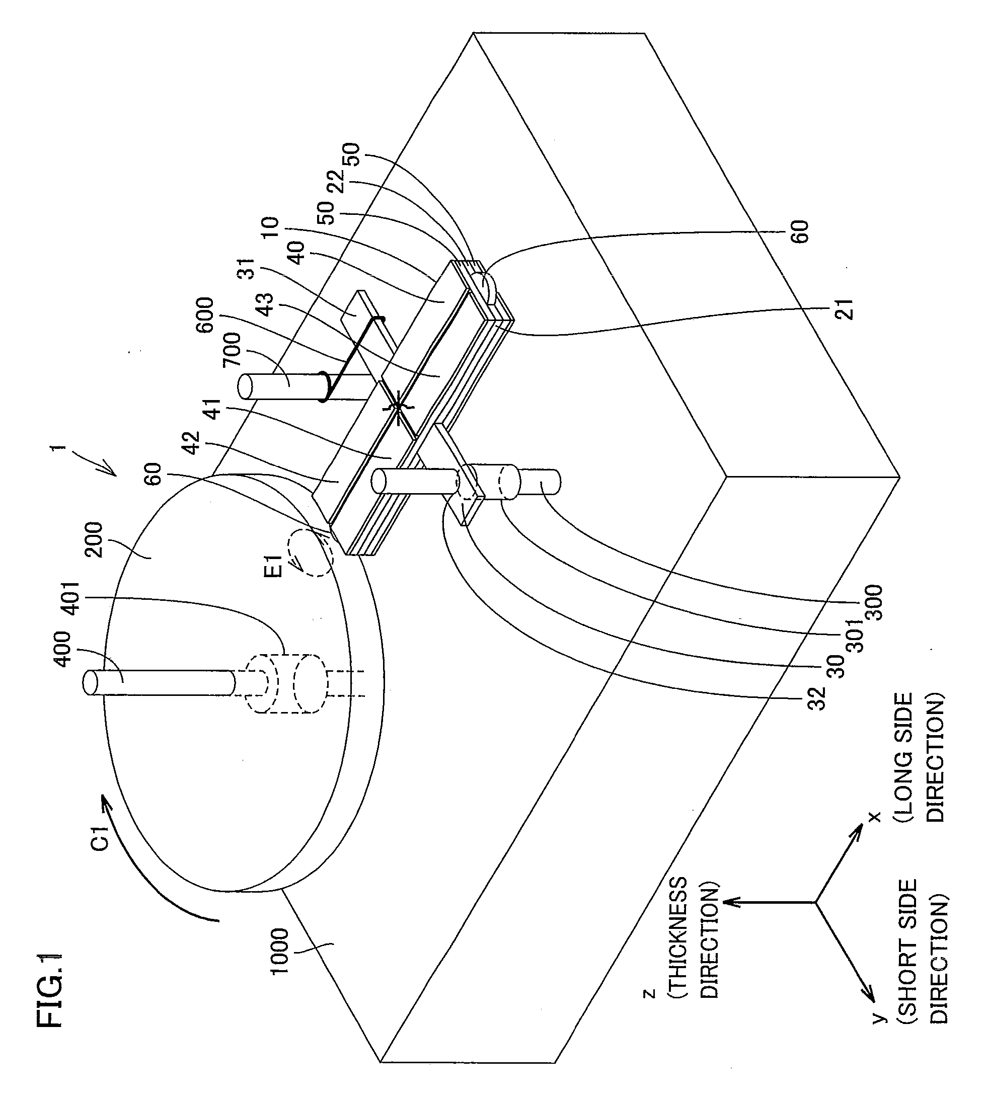
[0045]Referring to FIGS. 1 to 7, an ultrasonic motor 1 of a first embodiment will be described below.

[0046]As shown in FIG. 1, ultrasonic motor 1 of the first embodiment includes an ultrasonic vibrator 10 and a rotor 200 driven by ultrasonic vibrator 10. Ultrasonic motor 1 includes a vibrator support shaft 300 and a rotor support shaft 400 connected to a main body 1000 of a device.

[0047]Rotor 200 takes a circular plate-like form, and has a thickness of 1.5 mm and an outer diameter of 10 mm. Rotor support shaft 400 is arranged in the center of rotor 200. Rotor support shaft 400 is fixed to main body 1000. Rotor 200 is preferably made of stainless steel (SUS). A rotor support 401 is arranged on rotor support shaft 400 for adjusting a vertical position of rotor 200. Thereby, rotor 200 is supported at a predetermined height by rotor support 401. Rotor support 401 holds rotor 200 only in its z-direction, and does not affect the rotation of rotor 200 on the x-y plane.

[0048]

[0049]The whole...

second embodiment

[0079]Referring to FIGS. 8 to 10, description will be given on an ultrasonic motor 2 of the second embodiment of the invention. As shown in FIGS. 8 and 9, ultrasonic motor 2 includes an ultrasonic vibrator 11 and a rotor 201. Components that implement the same structures or functions as those of ultrasonic motor 1 in the first embodiment bear the same reference numbers, and description thereof is not repeated.

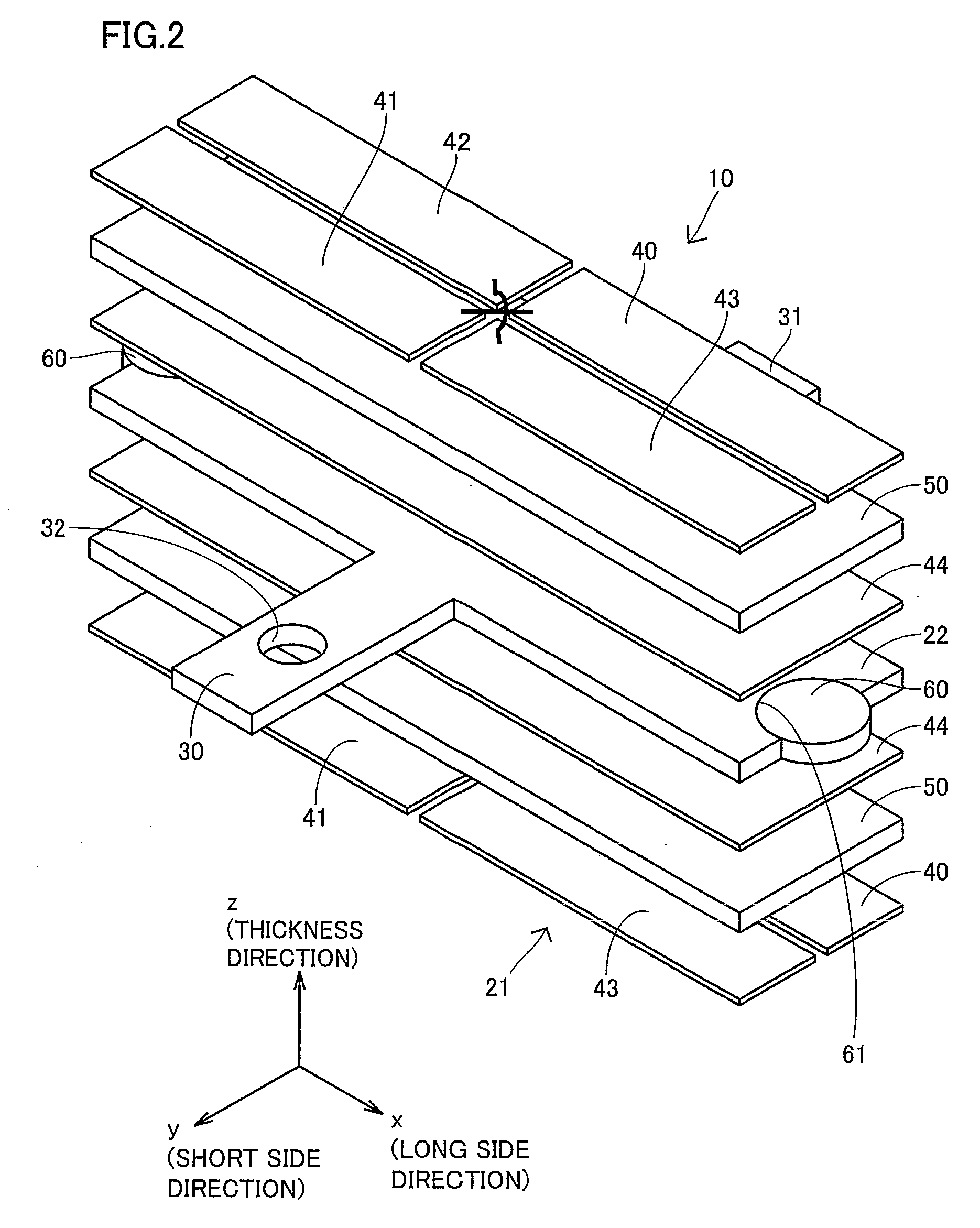
[0080]Ultrasonic vibrator 11 according to this embodiment includes piezoelectric element 50, electrodes 40, 41, 42, 43 and 44, and pushing projection 31 that have the same sizes and forms as the ultrasonic vibrator already described in connection with the first embodiment.

[0081]Ultrasonic vibrator 11 has a vibration plate 23. Vibration plate 23 has support projection 30 fixed to vibrator support shaft 300 and a main plate 24 that is formed integrally with support projection 30 for rotating rotor 201 by the vibration.

[0082]Main plate 24 is a plate-like member of a substantially ...

third embodiment

[0090]Referring to FIGS. 11 to 17, an ultrasonic motor 3 of the third embodiment of the invention will be described. Ultrasonic motor 3 includes two ultrasonic vibrators 12 of an arc-shaped plate type, a vibrator support shaft 302 and a rotor 202. Two ultrasonic vibrators 12 are mirror images of each other with respect to a predetermined plane containing a rotation axis of rotor 202 so that the following description will be given on only one of ultrasonic vibrators 12.

[0091]

[0092]Referring to FIG. 12, the structure of ultrasonic vibrator 12 will be described more in detail. As shown in FIG. 12, ultrasonic vibrator 12 of the arc-shaped plate type includes a vibration plate 25. Vibration plate 25 has a support portion 33 connected to vibrator support shaft 302 in a manner fashion restricting a translational motion and a rotary motion in all the directions, and also has a main plate 26 that is integral with support portion 33.

[0093]Main plate 26 is formed of an arc-shaped plate having ...


PUM


Abstract

An ultrasonic motor includes a driven object, a piezoelectric element for driving the driven object, a vibration plate including a notch having an inner peripheral surface of an arc-shaped form having a central angle larger than 180 degrees and being vibrated by the piezoelectric element, and a contact portion made of a material different from that of the vibration plate, having a portion overlapping the piezoelectric element in a plan view and being smaller in thickness than the piezoelectric element, attached to the notch of the vibration plate by press fitting or forced fitting and being in contact with the driven object. Thereby, the ultrasonic motor can have a high shock resistance and a high wear resistance, and can be driven with high efficiency.

Description

[0001]This nonprovisional application is based on Japanese Patent Application No. 2008-102387 filed on Apr. 10, 2008 with the Japan Patent Office, the entire contents of which are hereby incorporated by reference.BACKGROUND OF THE INVENTION[0002]1. Field of the Invention[0003]The present invention relates to an ultrasonic motor and the like.[0004]2. Description of the Background Art[0005]Ultrasonic motors having an ultrasonic vibrator that uses a vibration of a piezoelectric element have been used. The ultrasonic vibrator has such distinctive features that it is not affected by magnetism, is small in size, has a high torque, has a high response speed and is at rest when it is not energized. These and other features are different from those of an electromagnetic motor. Therefore, the ultrasonic motor is a potential element particularly for an autofocus drive mechanism of a small camera lens and the like.[0006]The piezoelectric element used in the ultrasonic vibrator is formed of a br...

Claims


Application Information

Patent Timeline
Patent Type & Authority Applications(United States)
IPC IPC(8): H02N2/12
CPCH02N2/003H02N2/103H02N2/004
Inventor KOTANI, TERUHISAHAMAMOTO, MASAKI
Owner SHARP KK
Why Eureka
Try Eureka