Magnetically suspended control moment gyro gimbal and locking control system

A technology for controlling torque gyroscopes and control systems, applied in magnetic attraction or thrust holding devices, electric traction, electric vehicles, etc., can solve problems such as heat dissipation, slow response speed, ultrasonic motor resonance mode shift, etc., to achieve Effects of protection from vibration and shock, stable performance, and faster response

Active Publication Date: 2011-04-13
BEIHANG UNIV
View PDF3 Cites 28 Cited by
  • Summary
  • Abstract
  • Description
  • Claims
  • Application Information

AI Technical Summary

Problems solved by technology

The existing frame torque motor control methods are divided into two control methods: three-loop control and two-loop control. The two-loop control mode is angular velocity loop and current loop. Since there is no angular position loop, it is difficult to achieve precise control of the angular position of the frame torque motor , so that high-precision control of the output torque direction of the magnetic levitation CMG cannot be realized; the response speed of the traditional three-loop control method is very slow, and the rapid maneuverability of the spacecraft cannot be realized, so the traditional frame torque motor control method cannot meet the high angular position and angular velocity. Unification of precision and fast response control
The locking device of the magnetic levitation CMG can protect the magnetic levitation rotor from being damaged by seve

Method used


Image

  • Magnetically suspended control moment gyro gimbal and locking control system
  • Magnetically suspended control moment gyro gimbal and locking control system
  • Magnetically suspended control moment gyro gimbal and locking control system

Examples


Embodiment Construction

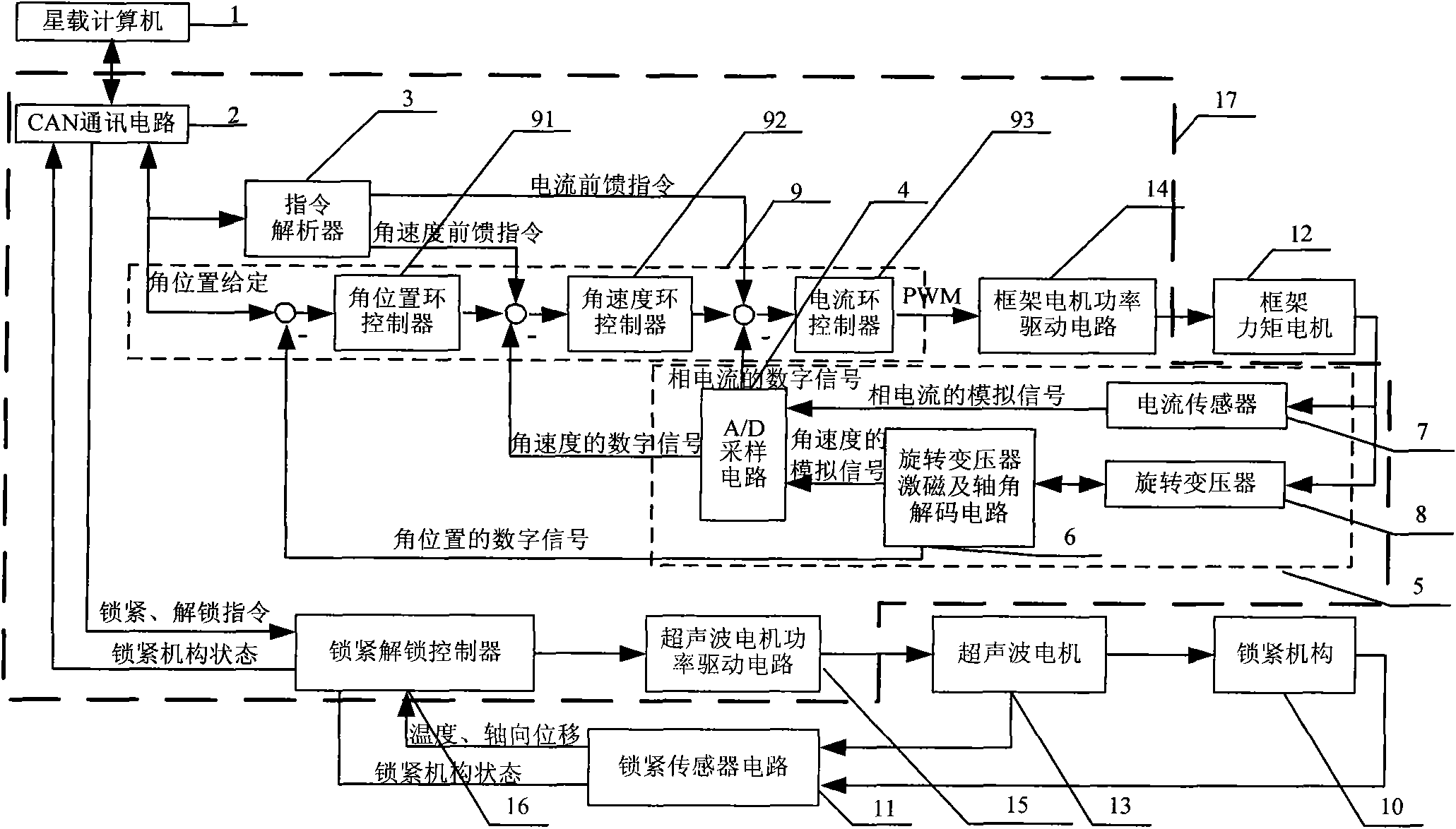
[0024] Such as figure 1As shown, the present invention includes frame torque motor 12, ultrasonic motor 13, locking mechanism 10, locking sensor circuit 11, DSP+FPGA numerical control device 17, wherein DSP+FPGA numerical control device 17 includes CAN communication circuit 2, instruction resolver 3 , frame controller 9, locking and unlocking controller 16, frame motor power drive circuit 14, ultrasonic motor power drive circuit 15, frame motor sensor circuit 5; frame motor sensor circuit 5 includes resolver excitation and shaft angle decoding circuit 6, rotation Transformer 8 , current sensor 7 , A / D sampling circuit 4 ; frame controller 9 includes an angular position loop controller 91 , an angular velocity loop controller 92 and a current loop controller 93 . The on-board computer 1 transmits the given angular position command and the locking and unlocking command to the frame controller 9 and the locking and unlocking controller 16 through the CAN communication circuit 2, ...


PUM


Abstract

The invention discloses a magnetically suspended control moment gyro gimbal and a locking control system. The magnetically suspended control moment gyro gimbal mainly comprises a gimbal moment motor, a locking mechanism, an ultrasonic motor, a locking sensor circuit and a digital signal processor (DSP) and field programmable gate array (FPGA) numerical control device, wherein the DSP and FPGA numerical control device comprises a controller area network (CAN) communication circuit, a command parser, a gimbal controller, a locking/unlocking controller, a gimbal motor power drive circuit, an ultrasonic motor power drive circuit and a gimbal motor sensor circuit; the gimbal controller performs the control of three closed loops and two feed forward according to an angle position, an angle speed, a current command value output by the CAN communication circuit and the command parser and a feedback value output by the gimbal motor sensor circuit to realize high precision and rapid response control of the gimbal moment motor; and the locking/unlocking controller selects the resonance frequency of the ultrasonic motor according to the temperature and an axial displacement value output by the locking sensor circuit and positively and negatively rotates the ultrasonic motor respectively according to locking and unlocking commands so as to lock or unlock the locking mechanism.

Description

technical field [0001] The invention relates to a magnetic levitation control torque gyro frame and a locking control system, which is used for high-precision, fast-response control of the magnetic levitation control torque gyro frame torque motor and the locking and unlocking control of the magnetic levitation control torque gyro, and is especially suitable for applications with high requirements Precision spacecraft control actuators with control accuracy, fast response speed, and high reliability. Background technique [0002] The control moment gyroscope (CMG) is the key actuator for the attitude maneuver of large spacecraft such as large satellites and space stations. CMG consists of a high-speed rotor system and a frame moment motor system. According to the different support methods of the high-speed rotor, it is divided into mechanical CMG and magnetic levitation CMG. The magnetic levitation CMG adopts the bearing support method of magnetic levitation. Compared with ...

Claims


Application Information

Patent Timeline
IPC IPC(8): B60L13/04H02N15/00
Inventor 房建成徐向波王志强薛立娟
Owner BEIHANG UNIV
Why Eureka
Try Eureka