Ultrasonic motor and electronic apparatus equipped with ultrasonic motor

a technology of ultrasonic motors and electronic devices, applied in piezoelectric/electrostrictive/magnetostrictive devices, piezoelectric/electrostrictive/magnetostrictive devices, piezoelectric/electrostrictive/magnetostriction machines, etc., can solve the problem of large detection frequency signal of drive frequency, achieve great magnitude, maintain drive force, and reduce the burden of phase shift circuits

Inactive Publication Date: 2006-02-28
SEIKO INSTR INC
View PDF12 Cites 30 Cited by
  • Summary
  • Abstract
  • Description
  • Claims
  • Application Information

AI Technical Summary

Benefits of technology

[0014]It is an object of the present invention to provide an ultrasonic motor and an electronic appliance with an ultrasonic motor which is capable of detecting a drive signal with a drive frequency component that is great relative t

Problems solved by technology

Also, the drive frequency signal is detected large relative to unwanted frequenci

Method used


Image

  • Ultrasonic motor and electronic apparatus equipped with ultrasonic motor
  • Ultrasonic motor and electronic apparatus equipped with ultrasonic motor
  • Ultrasonic motor and electronic apparatus equipped with ultrasonic motor

Examples


embodiment 1

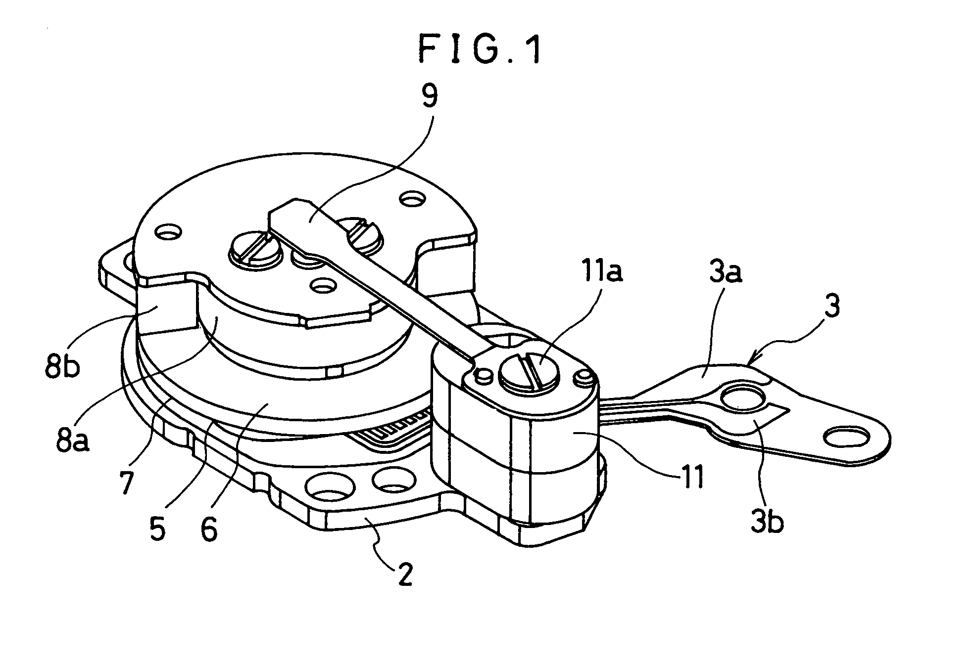
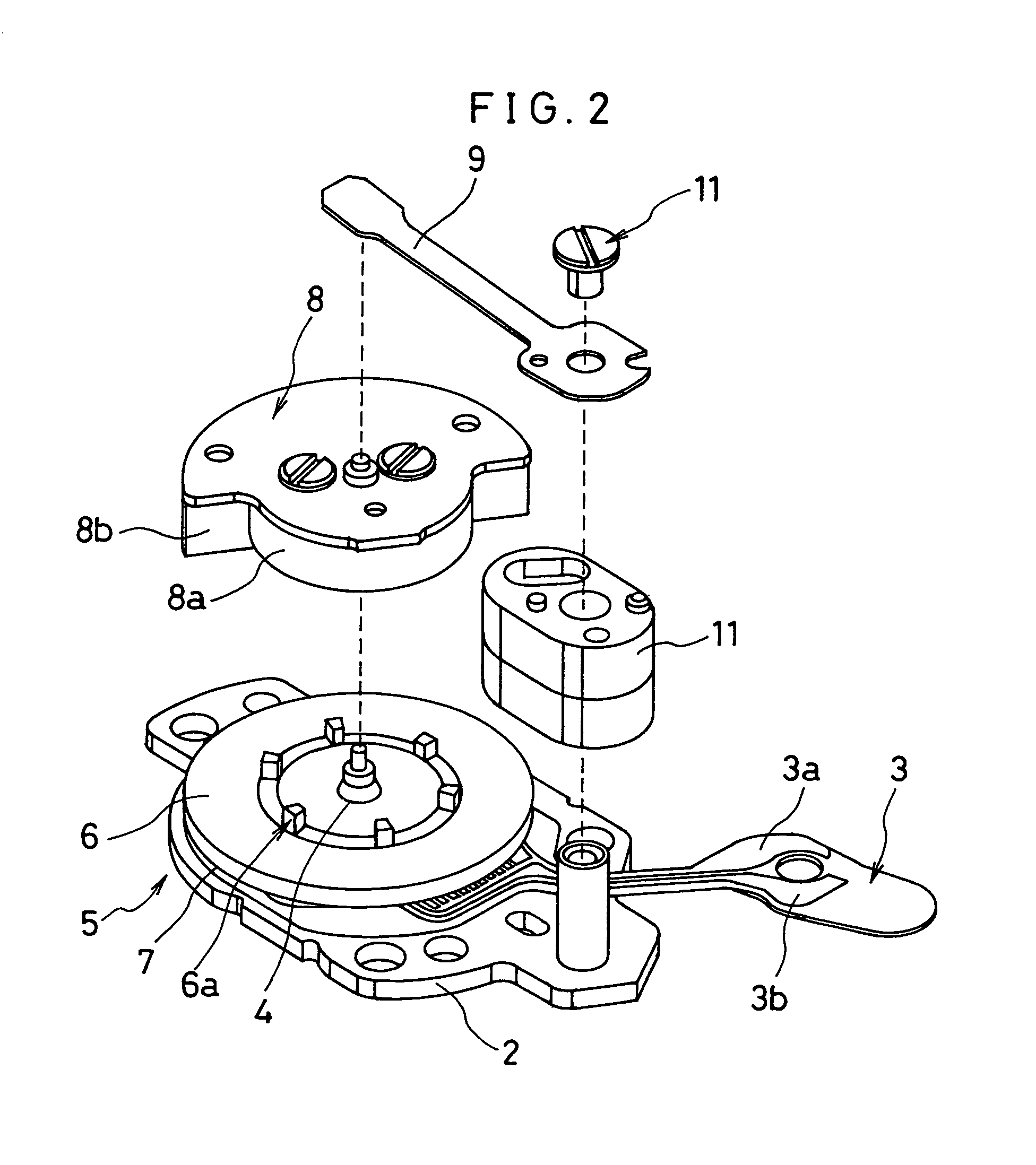
[0090]FIG. 1 is a perspective view of an ultrasonic motor according to Embodiment 1 to which the present invention is applied. FIG. 2 shows an exploded perspective view of the ultrasonic motor. FIG. 3 is an illustrative view showing a plan structure showing an electrode pattern 12, arrangement of projections 6a and operation of the projections 6a.

[0091]The ultrasonic motor comprises, as shown in FIG. 1 and FIG. 2, a support plate 2, a piezoelectric element lead 3, a central shaft 4 provided at a center of the support plate 2, a piezoelectric element vibrating member 5 fixed on the central shaft 4, a rotor unit 8 abutting against the piezoelectric vibrating member 5, a press spring 9 abutting against the rotor unit 8, and a press spring seat 11 for installing the press spring 9.

[0092]Here, the piezoelectric lead 3 is laid with a first lead 3a and second lead 3b formed of gold, copper or the like on a substrate of polyimide or the like.

[0093]The piezoelectric vibrating member 5 is st...

embodiment 2

[0129]FIG. 9 is a view showing a structure in a perspective direction of an ultrasonic motor according to a second embodiment to which the invention is applied. FIG. 10 shows a block diagram having a piezoelectric vibrating member with a drive circuit according to the present ultrasonic motor.

[0130]Embodiment 2 has generally in the same structure as Embodiment 1, wherein the feature lies in that the essential part is constituted by a piezoelectric vibrating member 16 and a rotor 19 placed in abutment against the piezoelectric vibrating member 16. Incidentally, the same structures as those of Embodiment 1 are denoted by the same reference characters, and further explanation is omitted.

[0131]The piezoelectric vibrating member 16 is formed by an elastic member 17 and a piezoelectric element 18 bonded to the elastic member 17. The elastic member 17 is circumferentially formed with a plurality of projections 17a on a disc member. Also, the piezoelectric element 18 is provided, similarly ...

embodiment 3

[0141]FIG. 11 is a view showing an essential part of an ultrasonic motor according to Embodiment 3 to which the invention is applied. FIG. 12 is a block diagram of a drive circuit of this ultrasonic motor. FIG. 13 is a view showing a positional relationship between a detecting polarized portion 27e and a detecting electrode 29c with respect to a vibration wave on a piezoelectric vibrating member 25.

[0142]This ultrasonic motor has generally the same structure as Embodiment 1, and is characterized by its piezoelectric vibrating member 25 and an annular rotor 28 placed in abutment against the piezoelectric vibrating member 25. Incidentally, the same structures are denoted by the same reference characters, and further explanation is omitted.

[0143]Here, the piezoelectric vibrating member 25 is formed by an elastic member 26 and a piezoelectric element 27 bonded to the elastic member 26. The elastic member 26 is formed with a plurality of projections 26a on an upper surface of an annular ...


PUM


Abstract

An ultrasonic motor comprises a piezoelectric vibrating member having a detecting polarized portion for detecting a drive signal having a drive frequency of the detecting polarized portion and a driving polarized portion for receiving the drive signal to oscillate the piezoelectric vibrating member in self-excited oscillation to produce a drive force. The detecting polarized portion is disposed at a portion of the piezoelectric vibrating member for undergoing maximum deformation in at least one vibration mode of oscillation of the piezoelectric vibrating member. An amplifying circuit amplifies the drive signal detected by the detecting polarized portion and inputs the amplified signal to the driving polarized portion to oscillate the piezoelectric vibrating member.

Description

BACKGROUND OF THE INVENTION[0001]The present invention relates to an ultrasonic motor which is provided with a detecting polarized portion for detecting a drive signal based on oscillation in a driving polarized portion, and more particularly to an ultrasonic motor and to an electronic apparatus or appliance having the ultrasonic motor having a detecting polarized portion to detect the drive signal with a drive frequency component that is great relative to unwanted frequency components.[0002]Recently, attention has been drawn to ultrasonic motors utilizing a piezoelectric-element having piezoelectric effects in the field of the micro-motors.[0003]An ultrasonic motor of this type is applied with an alternating current obtained generally in an external oscillation circuit, which adopts a method of detecting a phase difference in electric current or voltage in order to trace a resonant point that varies in response to change in the external environment, including temperature and load. ...

Claims


Application Information

Patent Timeline
IPC IPC(8): H01L41/08H02N2/00H01L41/04H01L41/09
CPCH01L41/0913H02N2/0015H02N2/004H02N2/166H02N2/106H02N2/145H02N2/163H02N2/0045H10N30/2023
Inventor IINO, AKIHIROKASUGA, MASAOSUZUKI, KENJI
Owner SEIKO INSTR INC
Why Eureka
Try Eureka