Elliptical cavity optical retinal display

a retinal display and elliptical cavity technology, applied in optics, instruments, static indicating devices, etc., can solve the problem of requiring considerable spa

Inactive Publication Date: 2001-06-26
UNITED STATES OF AMERICA THE AS REPRESENTED BY THE SEC OF THE ARMY
View PDF6 Cites 23 Cited by
  • Summary
  • Abstract
  • Description
  • Claims
  • Application Information

AI Technical Summary

Problems solved by technology

This arrangement requires considerable space, which is at a premium in head mounted displays.
The difficulty in this approach is the design of an optical delivery system which is consistent with the available methods of scanning and the requirements for total field of view and eye relief distance, all in a lightweight package.

Method used


Image

  • Elliptical cavity optical retinal display
  • Elliptical cavity optical retinal display
  • Elliptical cavity optical retinal display

Examples


Embodiment Construction

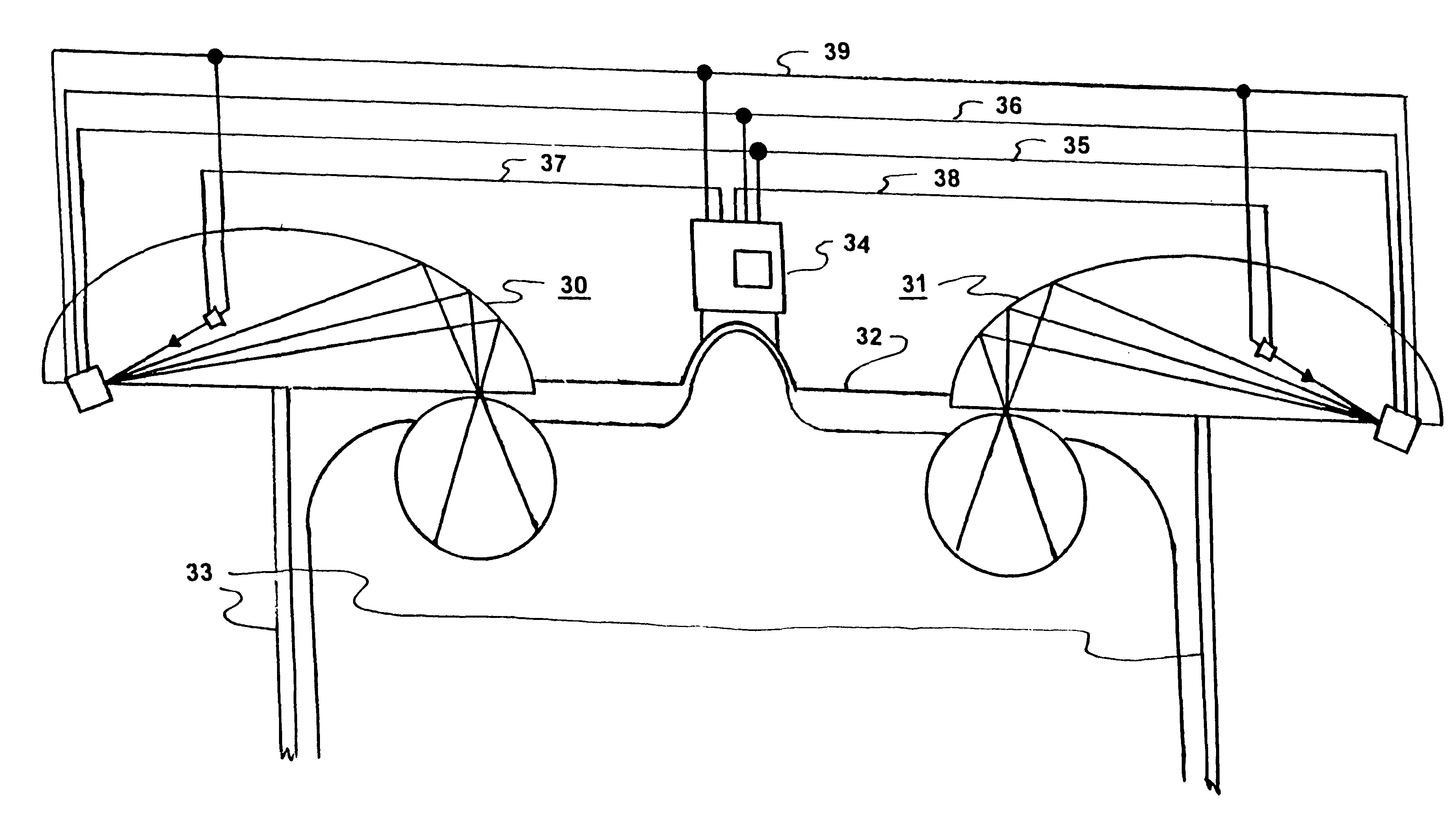
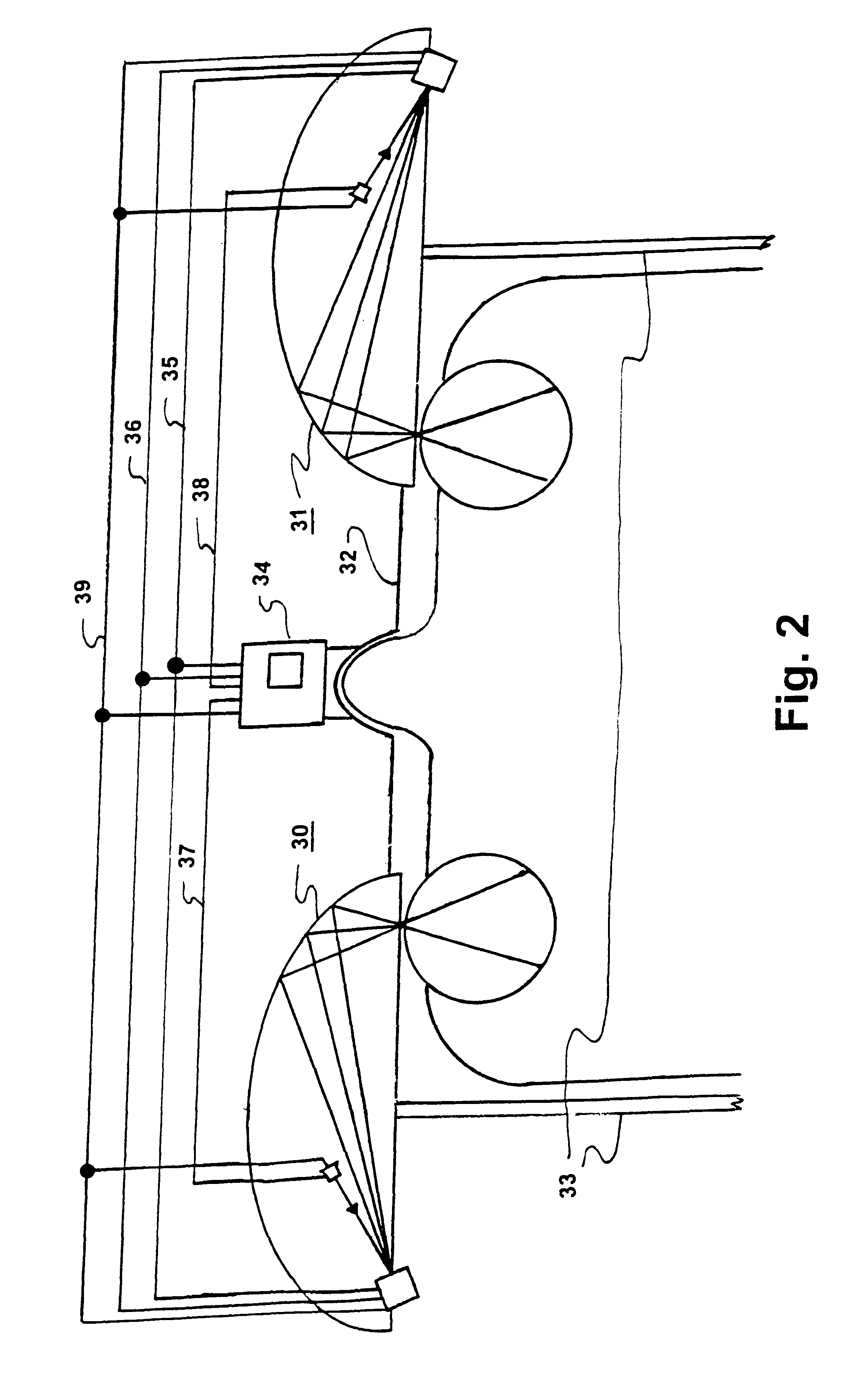
One embodiment of a display using the concept of direct retinal imaging for relaying video signal information to a human observer is disclosed in applicant's copending application Ser. No. 09 / 154,572 (NVL-3199), pending. That embodiment uses two, preferably, separate adjustably spaced parabolic light reflectors. The current embodiment uses a single elliptical light reflector. This reflector is supported by a portion of a shell with an inside surface generated by rotating an ellipse about its major axis. The shell may be opaque to improve light contrast, but a transparent shell permits a bright image to be projected on an ambient background, as will be shown.

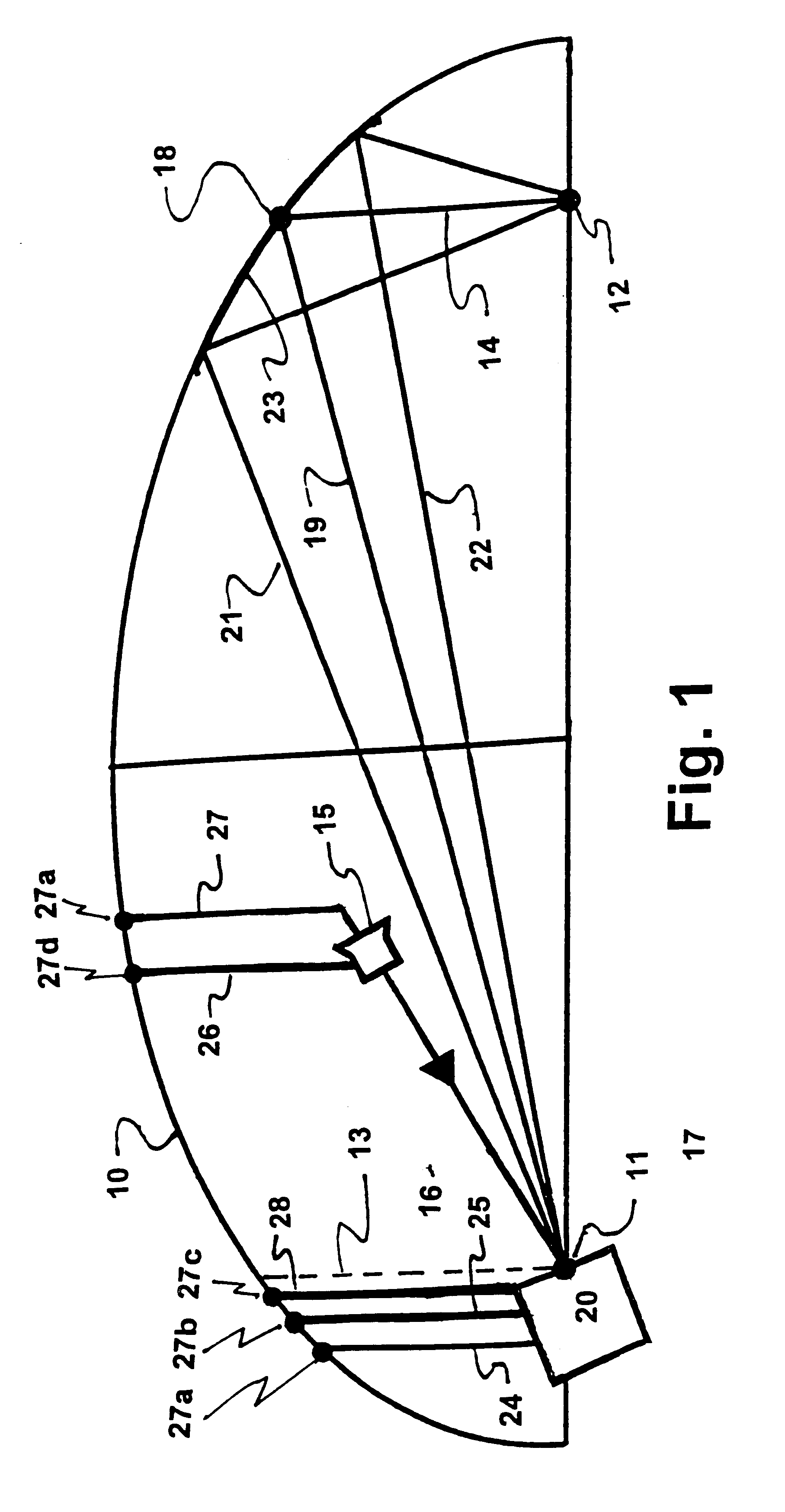
Referring specifically to FIG. 1 of the drawings a viewer module is shown that uses a shell portion 10 substantially equal to half the shell bisected by a cleaving plane through the major axis. The primary and secondary foci 11 and 12, respectively, are shown on this major axis. To establish an optical axis a reference plane is a...


PUM


Abstract

An opto-mechanical configuration for direct laser scanned retinal imaging is described. The concept uses simple geometric properties of an ellipse in a reflective optical delivery system which allows a small scanned laser beam to create a two dimensional video image directly on the retina of the human eye. The system is best suited for use in head-mounted display applications where light weight is a priority.

Description

1. Field of the InventionThe present invention generally relates to video displays wherein electronic video signals in standard TV format are converted into visible images for viewing by human eyes.2. Description of Prior ArtThe information gathered by state of the art sensors such as video cameras, near infra-red cameras, light intensification devices and far-infrared systems like the Forward Looking Infra-Red detector (FLIR) must be presented to the user by means of visible display. A particularly convenient holder for these displays is the head mounted type, resembling ordinary reading glasses or goggles; that leave the user's head, hands and in some cases his eyes free for other tasks. Conventional displays, whether Cathode Ray Tube (CRT), Flat Panel (including Liquid Crystal Displays, Light Emitting Diodes, etc.) or laser projectors, all produce real images on a screen which must be viewed either directly by the eye (such as the case in viewing a conventional CRT computer monit...

Claims


Application Information

Patent Timeline
Patent Type & Authority Patents(United States)
IPC IPC(8): G02B27/01G02B27/00
CPCG02B27/017G02B27/0172G02B2027/0132G02B2027/0178
Inventor HALL, JOHN M.
Owner UNITED STATES OF AMERICA THE AS REPRESENTED BY THE SEC OF THE ARMY
Why Eureka
Try Eureka