Method and apparatus for layer thickness measurement

a technology of layer thickness and measurement method, which is applied in the direction of manufacturing tools, instruments, transportation and packaging, etc., can solve the problems of difficult to quantify high installation and operation cost, and insufficient accuracy of absorption measurement of the thickness of the layer

Inactive Publication Date: 2007-04-05
NAT RES COUNCIL OF CANADA
View PDF6 Cites 21 Cited by
  • Summary
  • Abstract
  • Description
  • Claims
  • Application Information

AI Technical Summary

Benefits of technology

[0031] The laser source and detection equipment may be mounted on pan and tilt platforms. The platforms may be motorized for fine motion control. Preferably the tilt axes of the platforms are coaxial.

Problems solved by technology

Typically this has been accomplished by visual or tactile inspections, however this is undesirable for numerous reasons, including gaining access to the surfaces (if the surface is moving, the area is dangerous, etc.), time and expense, etc.
Further in marine environments icing and its detection may pose particular problems given inclusions of brine in the ice, which make thickness of the layer difficult to quantify.
For this reason they are expensive to install and operate.
Furthermore there are critical locations on structures, e.g. fuel tanks in wings, where embedded or manipulated sensors / emitters cannot, for practical reasons, be placed.
Furthermore absorption may not provide accurate enough an indication of thickness of the layer, in certain instances.
Accordingly rime ice or frosted glaze ice may not be detected or correctly measured using Pernick's system.
The effectiveness of this technique would be compromised considerably by the effect of inclusions (air bubbles, grain boundaries etc.) in the ice that influence the intensity of radiation detected by the sensor.
Furthermore the absorption qualities of water and ice are limitations on the wavelengths used for the system, and generally require more expensive sources.
Unfortunately using a band of wavelengths in spectral reflection or absorption techniques requires more expensive transmission and detection equipment.
Applicant's previous method was not ideally suited for measurements of less transparent layers such as rime ice.
Their range, i.e. distance of device from the surface, is fairly limited, and accordingly they are not applicable to aircraft ice detection and measurement, or for other distance measurements that are performed remotely.

Method used


Image

  • Method and apparatus for layer thickness measurement
  • Method and apparatus for layer thickness measurement
  • Method and apparatus for layer thickness measurement

Examples


Embodiment Construction

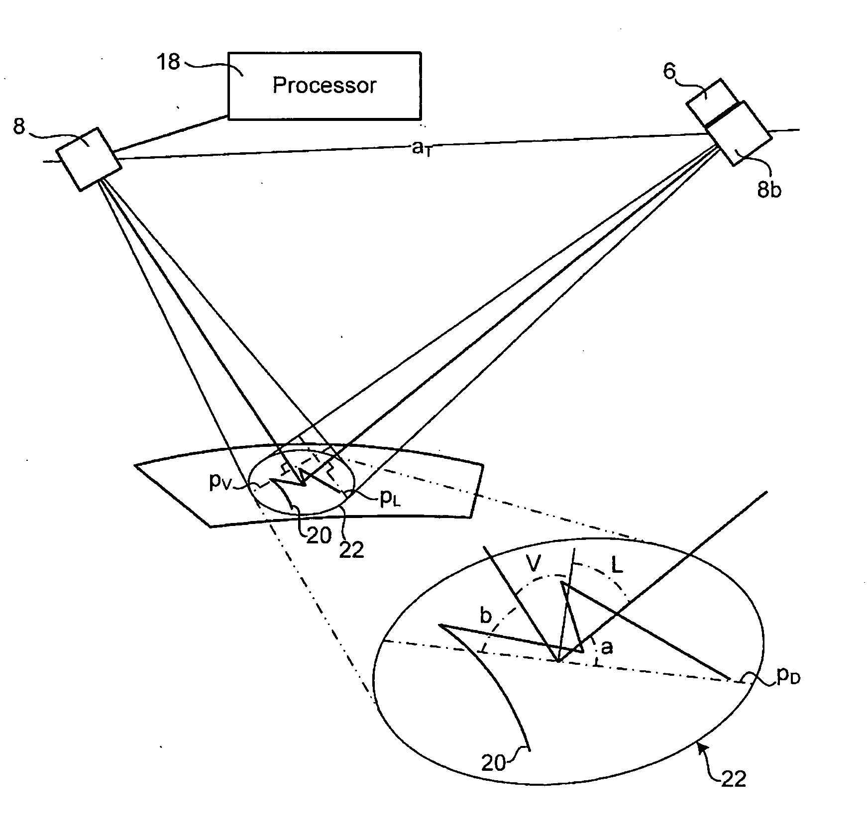
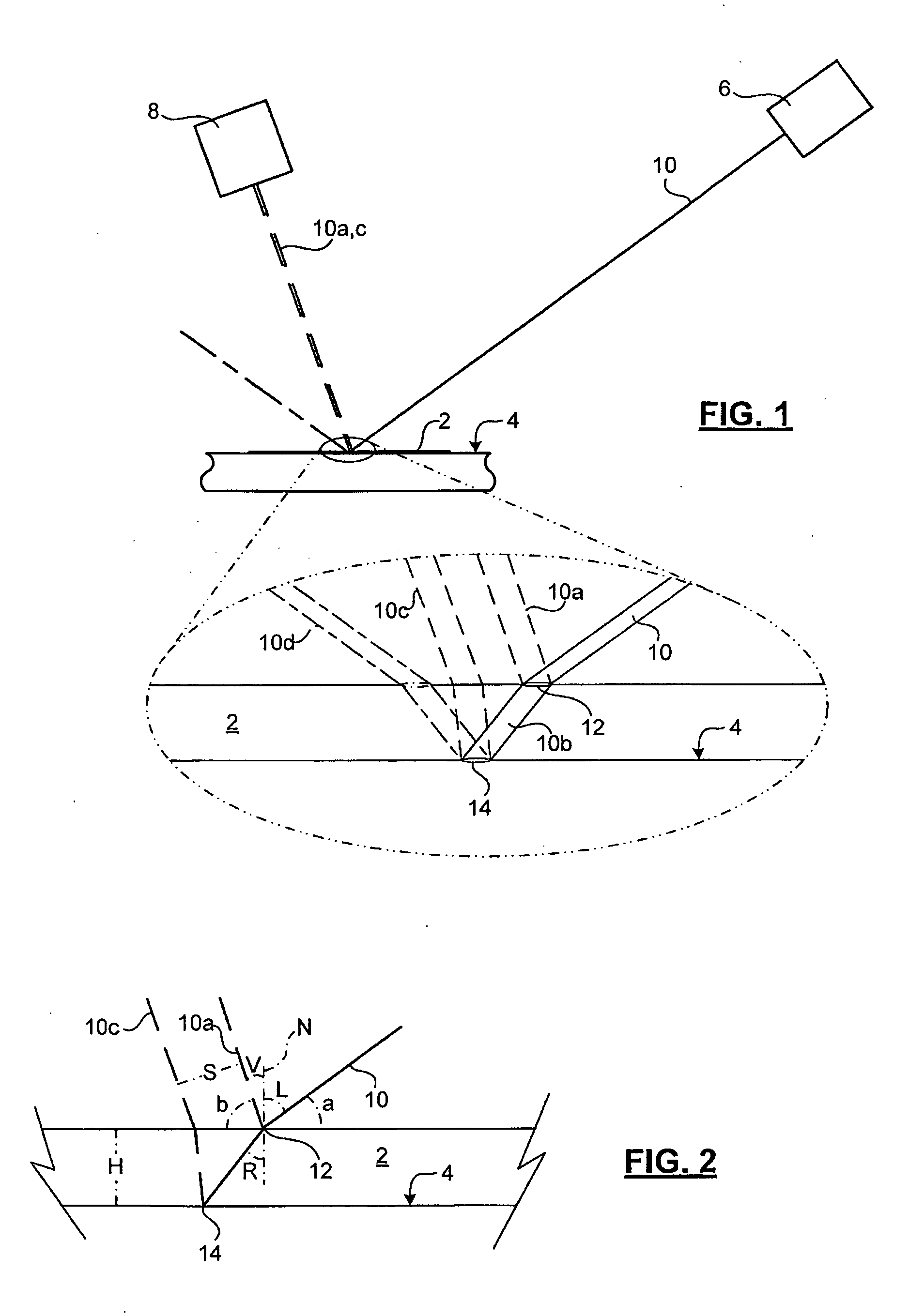
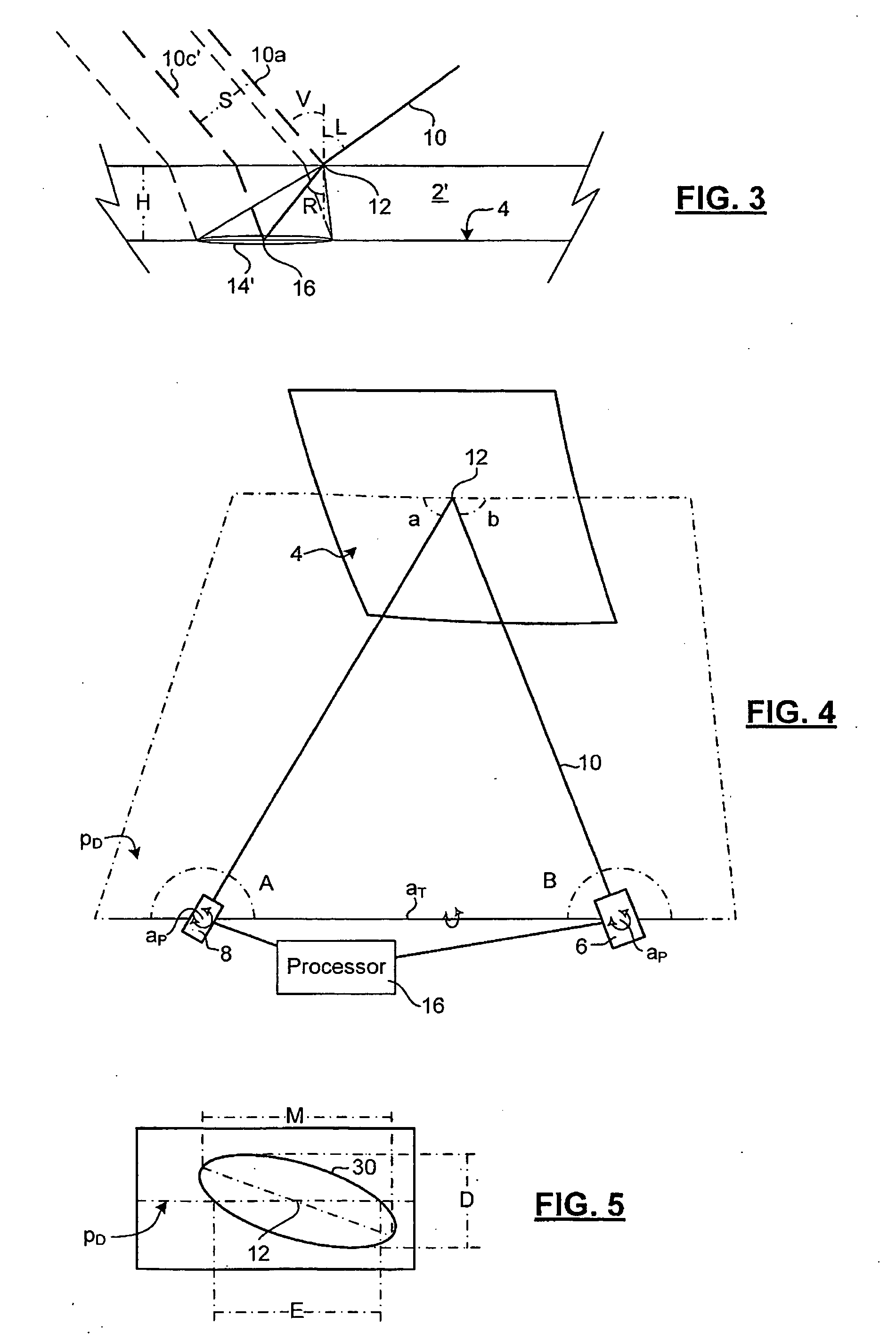
[0044] The invention provides a technique for detecting a layer on a surface, and if extant, measuring its thickness. The technique is designed to measure ice on a surface, such as an aircraft wing, a road surface, a marine structure (if the layer is thin enough), or ice of various optical properties that form on an external fuel tank of the space shuttle, for example.

[0045] The detection technique of the invention is schematically illustrated in FIG. 1. FIGS. 2 and 3 illustrate geometrical parameters of the system, and illustrate operation of the detection technique in the case of both transparent and diffusing layers 2 / 2′ on a surface 4. The apparatus for detection consists of a laser source 6, and a detector 8, such as a viewing apparatus. Advantageously the invention can be applied at distances requiring a telephoto lens or a telescope, for example, as a part of the viewing apparatus. Preferably the apparatus also includes a video camera, digital still camera, diode array, etc....


PUM


Abstract

A technique for optical measurement of a thickness of a layer on a surface uses diffuse reflections at opposite boundaries of the layer, operates on transparent, or translucent layers. The thickness is determined by computing a separation between the centers of the two diffuse reflections, and using the index of refraction of the layer, and geometric properties of a beam and detector with respect to the surface. The technique is useful for quantifying thickness of a layer of rime ice, glaze ice, frosted ice, or water, for example.

Description

CROSSREFERENCE TO RELATED APPLICATIONS [0001] This application claims domestic priority under 35 U.S.C. 119(e) from prior provisional application Ser. No. 60 / 721,996 filed Sep. 30, 2005, the entire contents of which is hereby incorporated by reference as if fully set forth herein.FIELD OF THE INVENTION [0002] The present invention relates in general to non-destructive, remote detection and measurement of layers, and in particular relates to measurement of thickness of a layer of transparent or optically-diffusive, translucent material (e.g. rime ice) on a surface. BACKGROUND OF THE INVENTION [0003] In the context of cold weather aeronautics, it is necessary to provide an accurate assessment of whether a surface of an aircraft is bare, or covered with a layer of solid and / or liquid deposits such as ice and water, and to quantify the deposits so that an appropriate measure can be taken to ensure safe use of the aircraft. Typically this has been accomplished by visual or tactile inspec...

Claims


Application Information

Patent Timeline
Patent Type & Authority Applications(United States)
IPC IPC(8): B23Q17/22
CPCB64D15/20G01B11/0625
Inventor GAGNON, ROBERT E.
Owner NAT RES COUNCIL OF CANADA
Why Eureka
Try Eureka