Three state branch history using one bit in a branch prediction mechanism

a branch prediction and one-bit technology, applied in the field of microprocessors, can solve the problems of increasing the accuracy of predictions is typically poorer than, and the complexity of the branch prediction mechanism is increased

Inactive Publication Date: 2001-06-26
GLOBALFOUNDRIES INC
View PDF37 Cites 88 Cited by
  • Summary
  • Abstract
  • Description
  • Claims
  • Application Information

AI Technical Summary

Problems solved by technology

Typically, increasing the accuracy of the branch prediction mechanism is achieved by increasing the complexity of the branch prediction mechanism.
Consequently, the accuracy of predictions is typically poorer than that of the two bit mechanism as will be discussed below.
However, the complexity of the branch prediction mechanism is increased by the need to select between additional branch predictions.
A problem related to increasing the complexity of the branch prediction mechanism is that the increased complexity generally requires an increased amount of time to form the branch prediction.
For example, selecting among multiple branch predictions may require a substantial amount of time.
As the number of branch predictions is increased, the complexity (and time required) for the selection logic increases.
The increased time may result in the introduction of one or more "bubbles" into the instruction processing pipeline during clock cycles that instructions cannot be fetched due to a lack of a branch prediction corresponding to a previous fetch address.
As mentioned above, while using more bits to record the history of a branch may increase the accuracy of predictions, the disadvantage of such a technique is the increased storage required for the additional bits increases the physical size and cost of the branch prediction storage.

Method used


Image

  • Three state branch history using one bit in a branch prediction mechanism
  • Three state branch history using one bit in a branch prediction mechanism
  • Three state branch history using one bit in a branch prediction mechanism

Examples


Embodiment Construction

illustrates the use of the byte range including only byte 0 of a group of contiguous instruction bytes. Example 80 shows an instruction IN0 ending at byte "E" of a first group of contiguous instruction bytes, a predicted branch PB0 extended from byte "F" of the first group to byte 0 of a second group of contiguous instruction bytes which are sequential to the first group, and an instruction IN1 beginning at byte "1" of the second group.

Since branch instruction PB0 does not end until byte 0 of the second group, the second group needs to be fetched from instruction cache 16. Therefore, the branch selector corresponding to bytes "E" and "F" of the first group indicates sequential, thereby causing the second group to be fetched. The sequential fetch address includes an offset portion set to zero (since bytes immediately subsequent to the last bytes of the first group are being fetched). Therefore, the branch selector corresponding to byte "0" of the second group is selected. The branch ...


PUM


Abstract

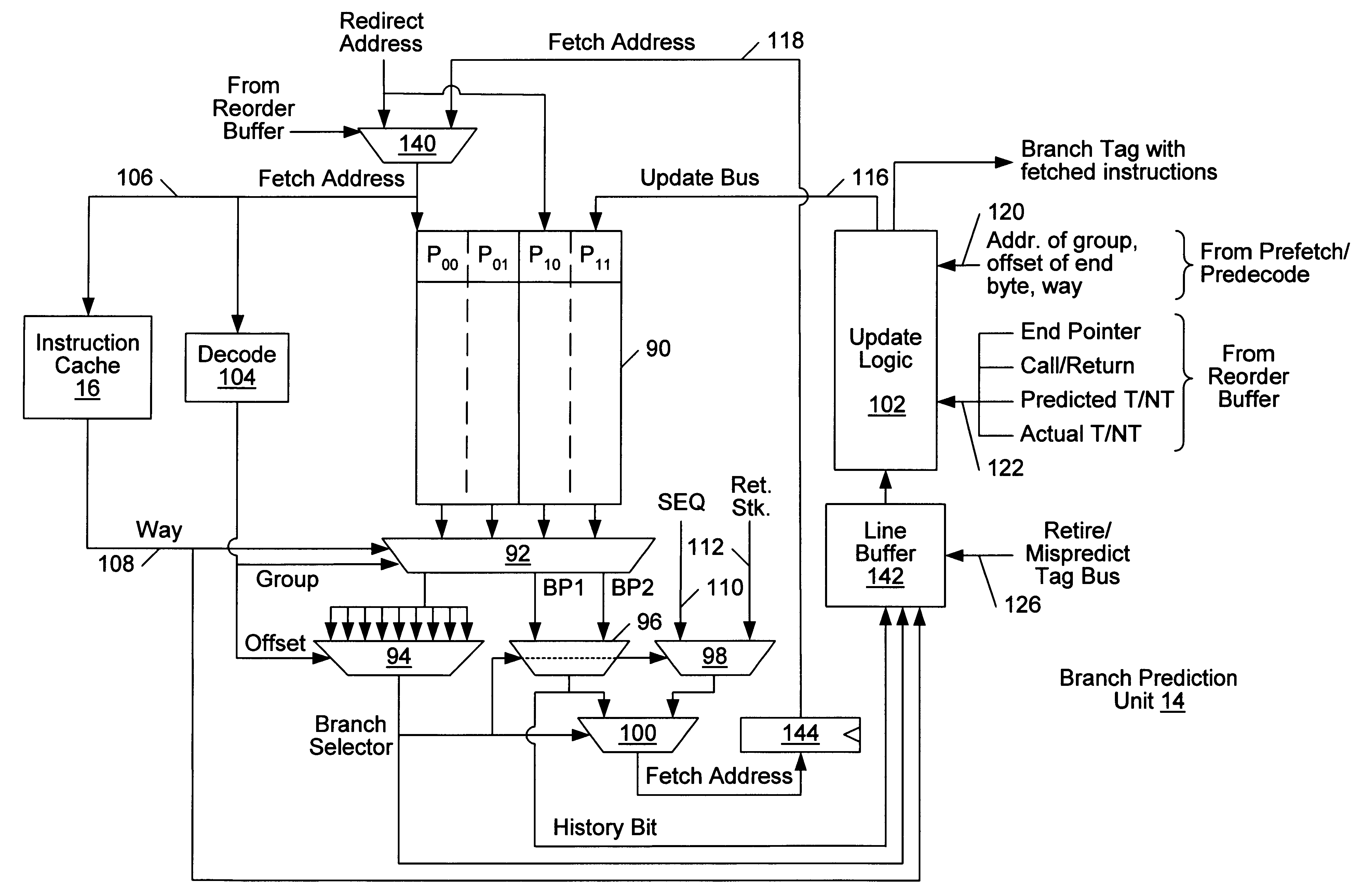
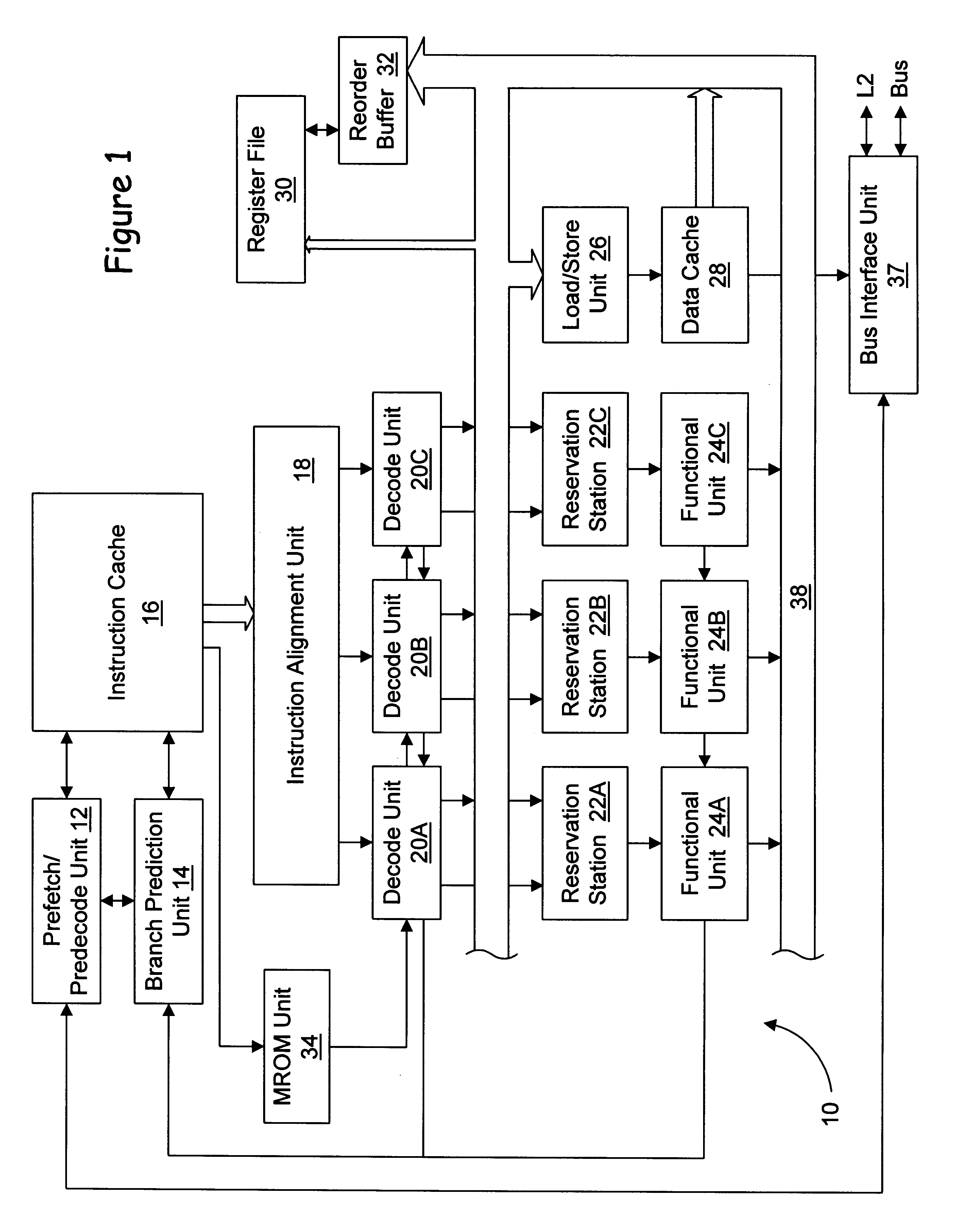
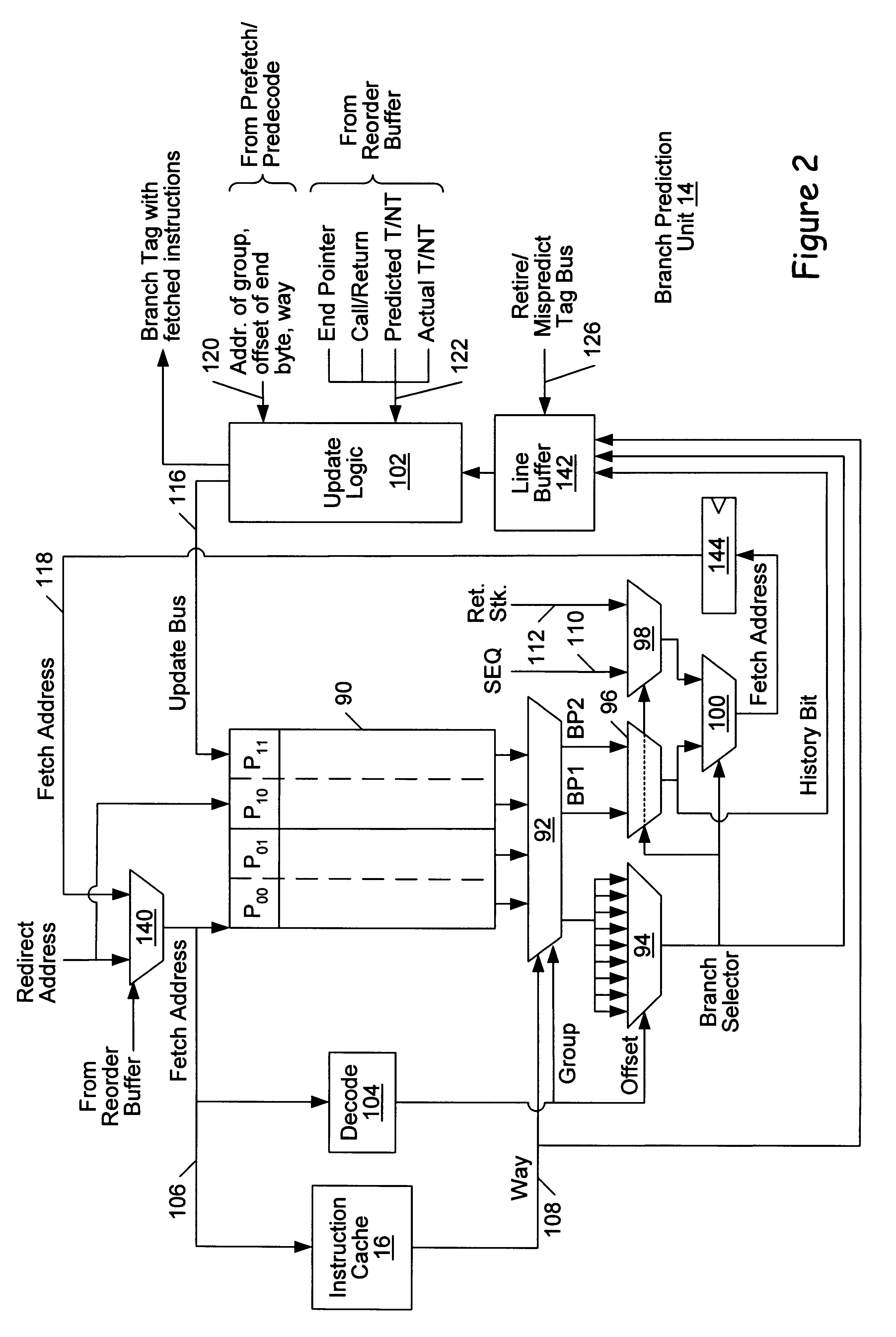
A branch prediction unit stores a set of branch prediction history bits and branch selectors corresponding to each of a group of contiguous instruction bytes stored in an instruction cache. While only one bit is used to represent branch prediction history, three distinct states are represented in conjunction with the absence of a branch prediction. This provides for the storage of fewer bits, while maintaining a high degree of branch prediction accuracy. Each branch selector identifies the branch prediction to be selected if a fetch address corresponding to that branch selector is presented. In order to minimize the number of branch selectors stored for a group of contiguous instruction bytes, the group is divided into multiple byte ranges. The largest byte range may include a number of bytes comprising the shortest branch instruction in the instruction set (exclusive of the return instruction). For example, the shortest branch instruction may be two bytes in one embodiment. Therefore, the largest byte range is two bytes in the example. Since the branch selectors as a group change value (i.e. indicate a different branch instruction) only at the end byte of a predicted-taken branch instruction, fewer branch selectors may be stored than the number of bytes within the group.

Description

1. Field of the InventionThis invention is related to the field of microprocessors and, more particularly, to branch prediction mechanisms within microprocessors.2. Description of the Related ArtSuperscalar microprocessors achieve high performance by executing multiple instructions per clock cycle and by choosing the shortest possible clock cycle consistent with the design. As used herein, the term "clock cycle" refers to an interval of time accorded to various stages of an instruction processing pipeline within the microprocessor. Storage devices (e.g. registers and arrays) capture their values according to the clock cycle. For example, a storage device may capture a value according to a rising or falling edge of a clock signal defining the clock cycle. The storage device then stores the value until the subsequent rising or falling edge of the clock signal, respectively. The term "instruction processing pipeline" is used herein to refer to the logic circuits employed to process ins...

Claims


Application Information

Patent Timeline
Patent Type & Authority Patents(United States)
IPC IPC(8): G06F9/38
CPCG06F9/3806G06F9/3844G06F9/30054
Inventor TRAN, THANG M.MCBRIDE, ANDREWMUTHUSAMY, KARTHIKEYAN
Owner GLOBALFOUNDRIES INC
Why Eureka
Try Eureka