Holding device for sealed insertion of cables through enclosure walls

a technology of holding device and enclosure wall, which is applied in the direction of lead-in/lead-through insulators, electrical appliances, insulators, etc., can solve the problems of difficult manufacture and mounting, complicated arrangement of known holding devices, and inability to pull out backwards

Inactive Publication Date: 2001-07-10
FRIEDRICH LUTZE
View PDF3 Cites 21 Cited by
  • Summary
  • Abstract
  • Description
  • Claims
  • Application Information

AI Technical Summary

Benefits of technology

to provide a simpler holding device of the aforementioned type, where in each opening cables with different cross-sections can be used and secured with a tight seal.

Problems solved by technology

The disadvantage of the known holding device is, on the one hand, that the strain relief is only effective for a very specific cable cross-section, so that cables with different cross-sections necessitate a very complicated arrangement including an exact adjustment of the openings with the respective cable cross-sections.
A further disadvantage is that after the cable gets jammed, it cannot be pulled out backwards; for example, if the wrong cable was inserted accidentally.
Finally, the known holding device is complicated and awkward to manufacture and mount, due to the high number of required plates, which also has cost disadvantages.

Method used


Image

  • Holding device for sealed insertion of cables through enclosure walls
  • Holding device for sealed insertion of cables through enclosure walls
  • Holding device for sealed insertion of cables through enclosure walls

Examples


Embodiment Construction

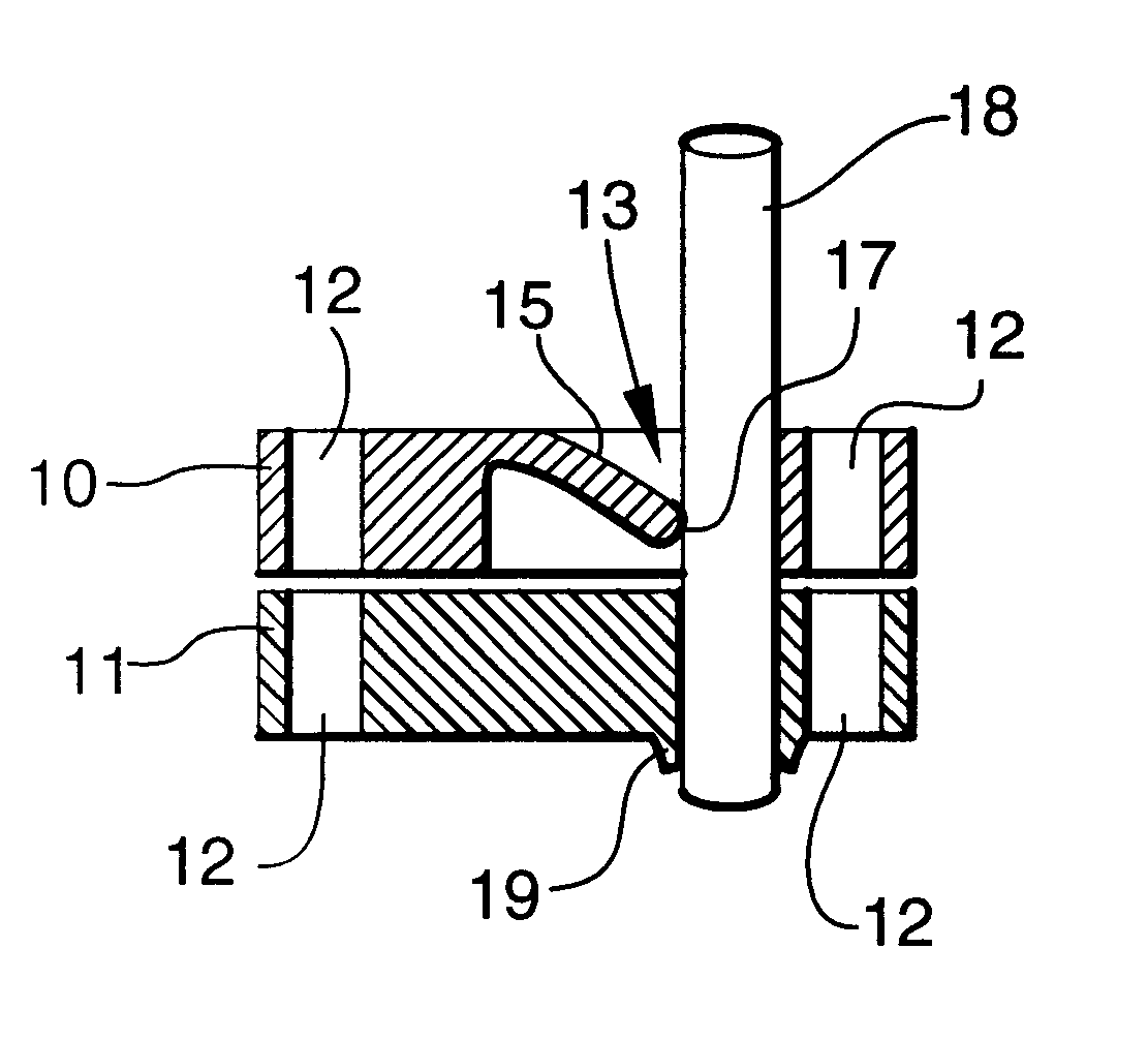
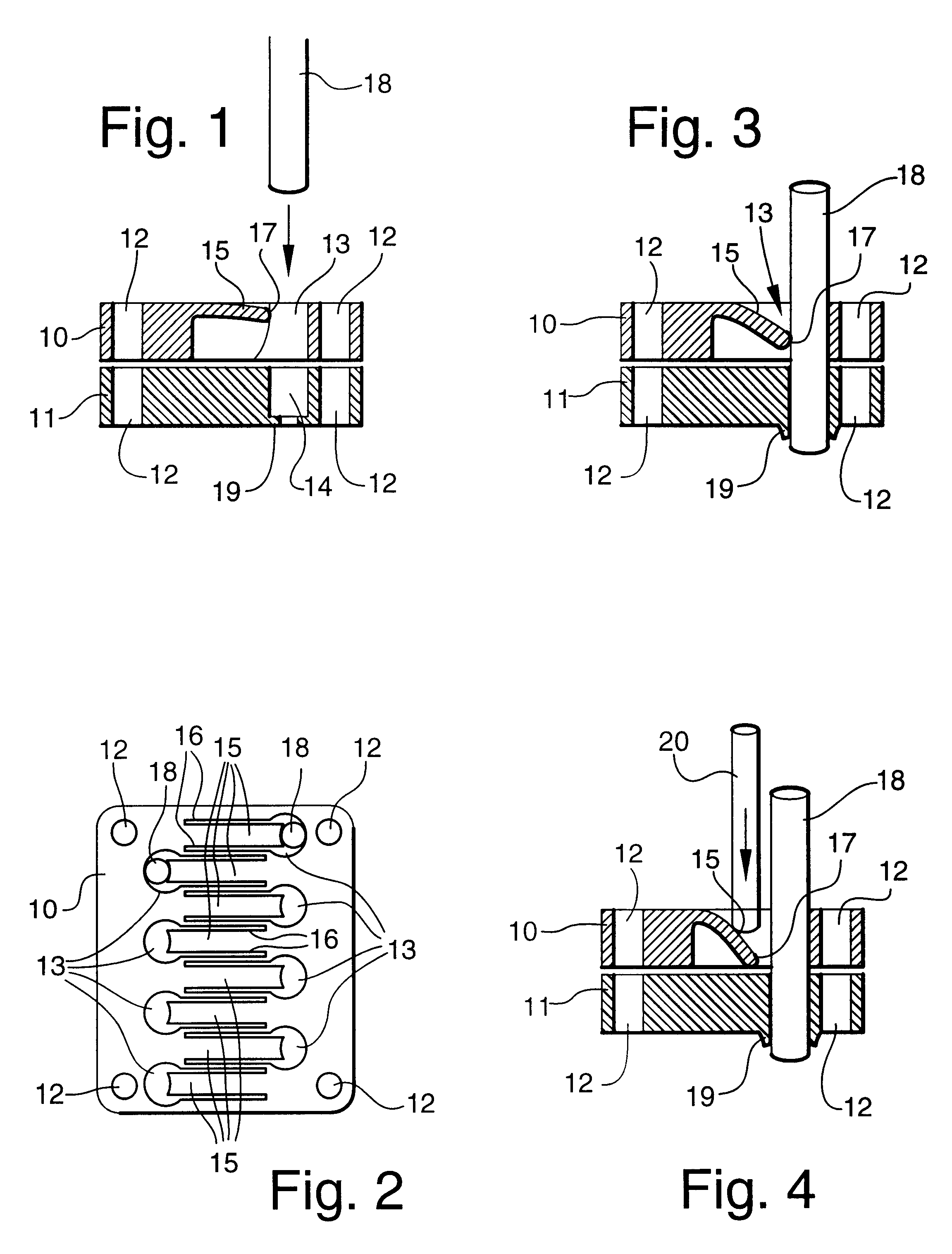
Referring now specifically to the drawings, a holding device as shown in FIG. 1 to 4 as the first exemplary embodiment comprises a basically rigid holding plate 10 made of metal or plastic and a sealing plate 11 made of an elastic, flexible material, for example neoprene, and having basically the same outer contours. In the four comer areas the basically rectangular plates 10, 11 have mounting holes 12, so that he holding plate 10 can be screwed 20 to an enclosure wall, which is not shown, by means of screws, which are not shown, so that the sealing plate 11 is located between them, forming a seal. This enclosure wall can be the wall of a control panel enclosure, a housing, a connection socket, or similar, and the holding device can be used any place where sealed insertion of a cable through a wall with simultaneous strain relief is required.

The holding plate 10 has eight cable openings 13, which are arranged in two rows and which are in true alignment with blind holes 14 in the sea...


PUM

PropertyMeasurementUnit
tensile strainaaaaaaaaaa
springy elasticityaaaaaaaaaa
flexibleaaaaaaaaaa

Abstract

A holding device for sealed insertion of cables (18) through enclosure walls, having a holding plate with several cable lead-through openings (13), which can be mounted on the enclosure wall also having cable lead-through openings, and an elastic sealing plate (11), which in the mounted state is located between the holding plate (10) and the enclosure wall. The sealing plate (11) has pre-manufactured cable perforation points (14) in true alignment with the cable lead-through openings (13). Furthermore, the holding plate has flexible holding tabs (15) extending sideways into the cable lead-through openings (13), and each of the tabs is deflected toward the enclosure wall if a cable (18) is inserted into the appropriate cable opening (13) and, if tensile strain is placed upon the cable (18), digs into the cable in the opposite direction, whereby the deflection toward the wall remains. With this holding device, cables (18) with different cross-sections can be held in the same cable openings (13), and simple unfastening for pulling out the cable is also possible.

Description

TECHNICAL FIELD AND BACKGROUND OF THE INVENTIONThis invention relates to a holding device for sealed cable insertion through enclosure walls, having a holding plate with several cable lead-through openings, which can be mounted on the enclosure wall also having cable lead-through openings, and an elastic sealing plate, which in the mounted state is located between the holding plate and the enclosure wall, having pre-manufactured cable perforation points in true alignment with the cable lead-through openings.In such a holding device, which is known for example from CH 688 012, a flexible plate is placed between a retainer plate and a counter plate, whereby these three plates are secured on a housing wall by means of a flange. After sealed insertion of the cable, it is pulled back slightly, so that the area of the flexible plate surrounding the cable is pulled into the retainer plate lead-through opening having a smaller diameter, where it gets jammed. This provides the desired cable ...

Claims


Application Information

Patent Timeline
Patent Type & Authority Patents(United States)
IPC IPC(8): H02G3/08
CPCH02G3/088
Inventor KASSULAT, BERND
Owner FRIEDRICH LUTZE
Why Eureka
Try Eureka