
Independently operating and mobile radiator and process for its manufacture

a technology for operating and moving radiators, which is applied in the direction of domestic stoves or ranges, heating types, lighting and heating apparatus, etc., can solve the problems of high shipping costs and inconvenience of heavy radiators, and achieve the effect of high shipping costs

Inactive Publication Date: 2001-07-17
DE LONGHI SPA
View PDF17 Cites 16 Cited by
  • Summary
  • Abstract
  • Description
  • Claims
  • Application Information

AI Technical Summary

Benefits of technology

Moreover, the above described prior art radiators have the inconvenience of being heavy which entails high shipping costs and is a hindrance for the end user when moving the radiator around the room.
The aim of the present invention is to eliminate the above inconveniences of the prior art radiators operating with diathermal oil.
An important object of the invention is to provide an independently operating and mobile radiator and a process for its manufacturing allowing a considerable saving of material for the manufacture of the radiator and thereby a lower weight of the radiator and easier handling by the user.
A further object of the invention is to provide an independently operating and mobile radiator and a process for its manufacture allowing the grid to be located directly on the upper portion of the radiating members of the radiator casing in order to eliminate any supplemental manufacture step and to reduce the manufacturing cost and therefore the retail cost of the radiator.
Still a further object of the invention is to provide an independently operating and mobile radiator and a process for its manufacturing allowing a greater circulation of ambient air and accordingly less time required to heat the room and a better overall efficiency of the radiator.

Problems solved by technology

Moreover, the above described prior art radiators have the inconvenience of being heavy which entails high shipping costs and is a hindrance for the end user when moving the radiator around the room.

Method used


Image

  • Independently operating and mobile radiator and process for its manufacture
  • Independently operating and mobile radiator and process for its manufacture
  • Independently operating and mobile radiator and process for its manufacture

Examples


Embodiment Construction

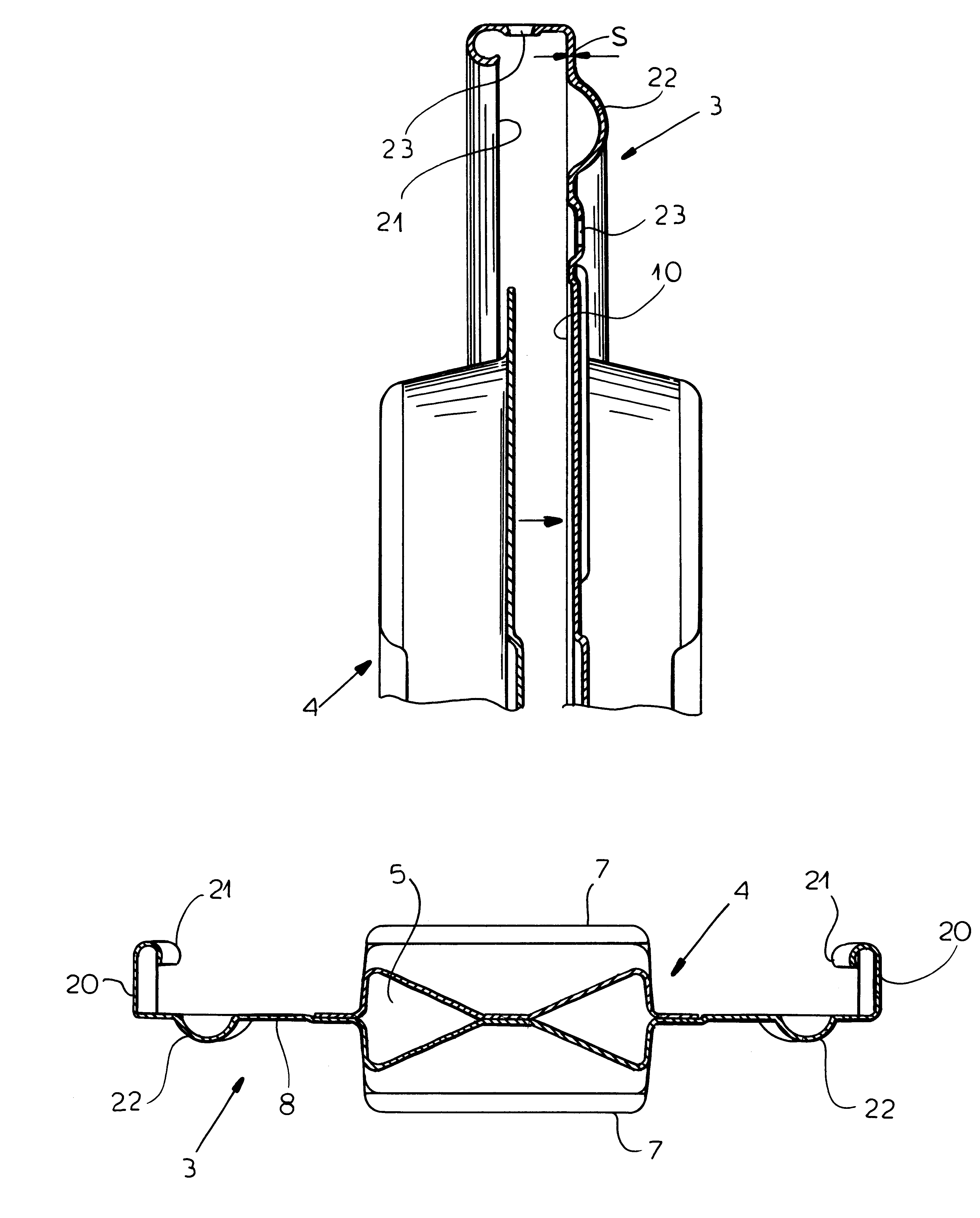
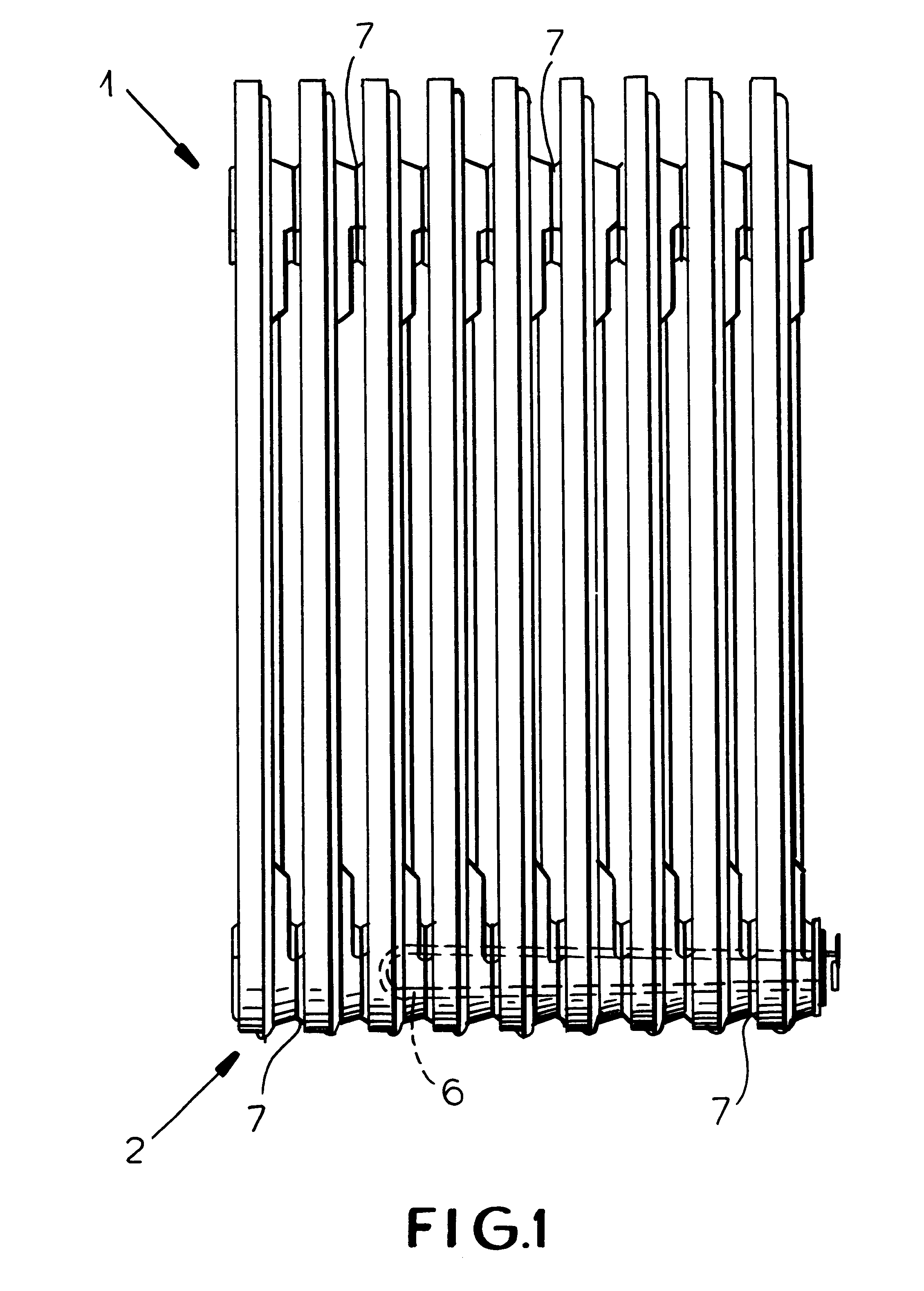
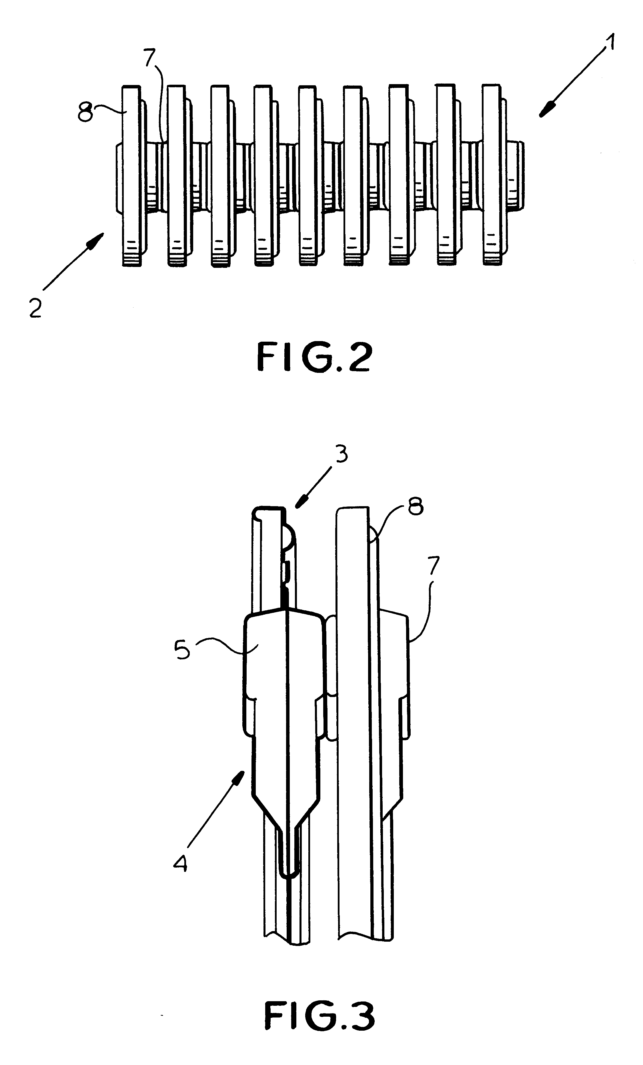
With reference to the above figures, the independently operating and mobile radiator, globally designated by the reference numeral 1, comprises a body 2 defined by a plurality of radiating members each defined by at least a first metal plate and a second metal plate, globally designated by the reference numerals 3 and 4, and by at least one central portion 5 wherein fluid heated at a preset temperature by heating means, namely a resistance 6, circulates.

The radiating members mutually communicate through hubs 7 for the passage of heated fluid, for example a diathermal oil, allowing the fluid to internally circulate inside the body 2 of the radiator.

Advantageously, each radiating member has at least one region of its surface 8 external to the central portion 5 where the diathermal oil circulates, having a wall thickness "S" substantially equal to the wall thickness of the first or second metal plates 3 or 4.

In particular (FIGS. 6 to 8), the wall thickness "S" is made equal to the wall...


PUM


Abstract

The independently operating and mobile radiator including a body having a plurality of radiating members each defined by a first metal plate and a second metal plate mutually associated and by a central portion wherein heated fluid circulates at a temperature preset by a resistance, the radiating members are mutually connected through passage hubs for circulating the heated fluid inside said body, each radiating member has one region of its surface, external to the central portion, having a wall thickness equal to the thickness of the first and second metal plates.

Description

1. Field of the InventionThe present invention relates to an independently operating and mobile radiator and to a process for manufacturing the radiator.2. Description of the Prior ArtAt present, as known, there are several types of independently operating and mobile radiators such as radiators wherein circulating diathermal oil is heated by an electric resistance arranged inside the radiator casing.These diathermal oil radiators usually have a number of radiating members mutually hydraulically connected by means of upper and lower hubs.Each radiating member is constituted by a first metal plate and a second metal plate mutually associated in order to define a central portion wherein the diathermal oil circulates. In each radiating member, the surface portion extending outside the central portion where the oil circulates may have folds and / or channels and / or apertures on the double sheet metal defined by the mutual connection of the first and second plates. Those folds and / or channe...

Claims


Application Information

Patent Timeline
Patent Type & Authority Patents(United States)
IPC IPC(8): F24H3/00F28D1/02F28D1/03F28F3/08F24H3/06F28D1/00
CPCF24H3/004F28D1/0333F28F2265/10F28D1/00
Inventor DE' LONGHI, GIUSEPPE
Owner DE LONGHI SPA
Learn More