Catheter with distally distending balloon

a balloon catheter and balloon technology, applied in catheters, other medical devices, surgery, etc., can solve problems such as irritating the opposing surfaces of the body cavity

Inactive Publication Date: 2001-07-24
KIMBERLY-CLARK WORLDWIDE INC
View PDF15 Cites 133 Cited by
  • Summary
  • Abstract
  • Description
  • Claims
  • Application Information

AI Technical Summary

Benefits of technology

It is, therefore, an object of the present invention to provide a balloon catheter whose inflated balloon isolates a portion of the distal tip and thereby protects opposing internal cavity surfaces from irritation.
These objects are generally accomplished by an inventive balloon catheter having a stiff distal tip to aide insertion of the catheter through a stoma or other opening to a body cavity. Immediately proximal to the tip is a shaft, and disposed upon the shaft in coaxial relationship is a balloon. Upon inflation of the balloon through an inflation lumen in the shaft, the distal end of the balloon distends over the stiff tip to protect an opposing wall of the body cavity in which the tip, balloon, and part of the shaft are located. The distal end of the inflated balloon has much greater surface area and is more resilient than the distal tip. The balloon thus, shields the opposing wall from potential irritation which could possibly be caused by the stiff distal tip.
In a third preferred embodiment, the uninflated balloon is longer than the portion of the shaft to which it is glued. This creates a longitudinal excess that allows the balloon to overlap the glue cuffs and distend longitudinally upon inflation. As in the previously described embodiment, the proximal wall enhances distal distention of the balloon

Problems solved by technology

The presence of a stiff catheter tip in this environment, has been suspected of irritating the opposing surfaces of the body cavity.

Method used


Image

  • Catheter with distally distending balloon
  • Catheter with distally distending balloon
  • Catheter with distally distending balloon

Examples


Embodiment Construction

Reference will now be made to the drawings wherein like structures will be provided with like reference numerals.

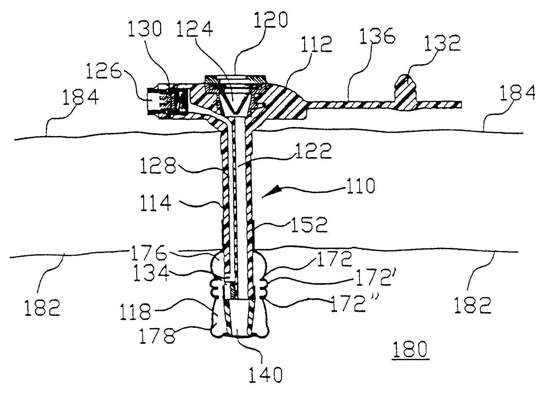
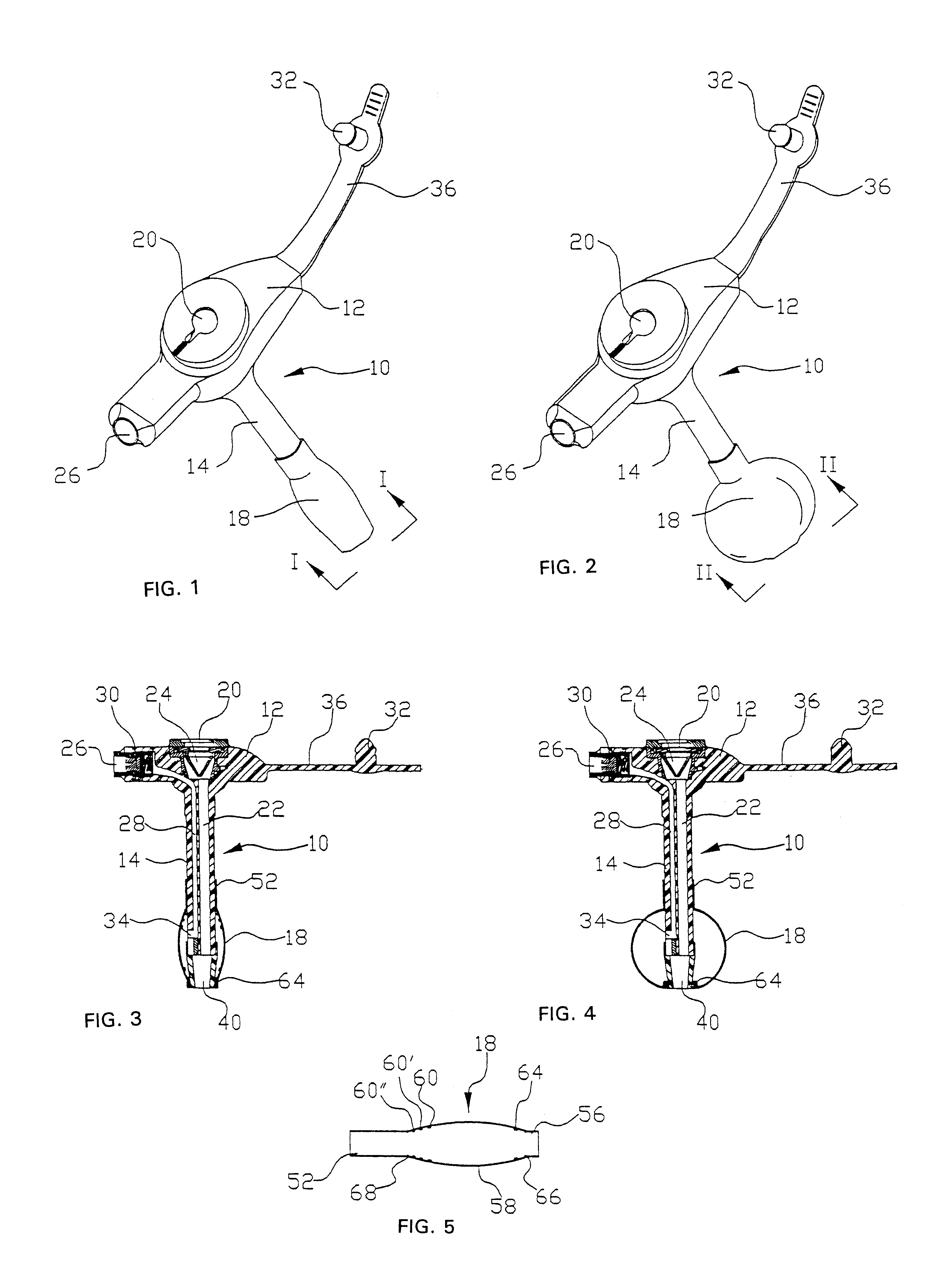
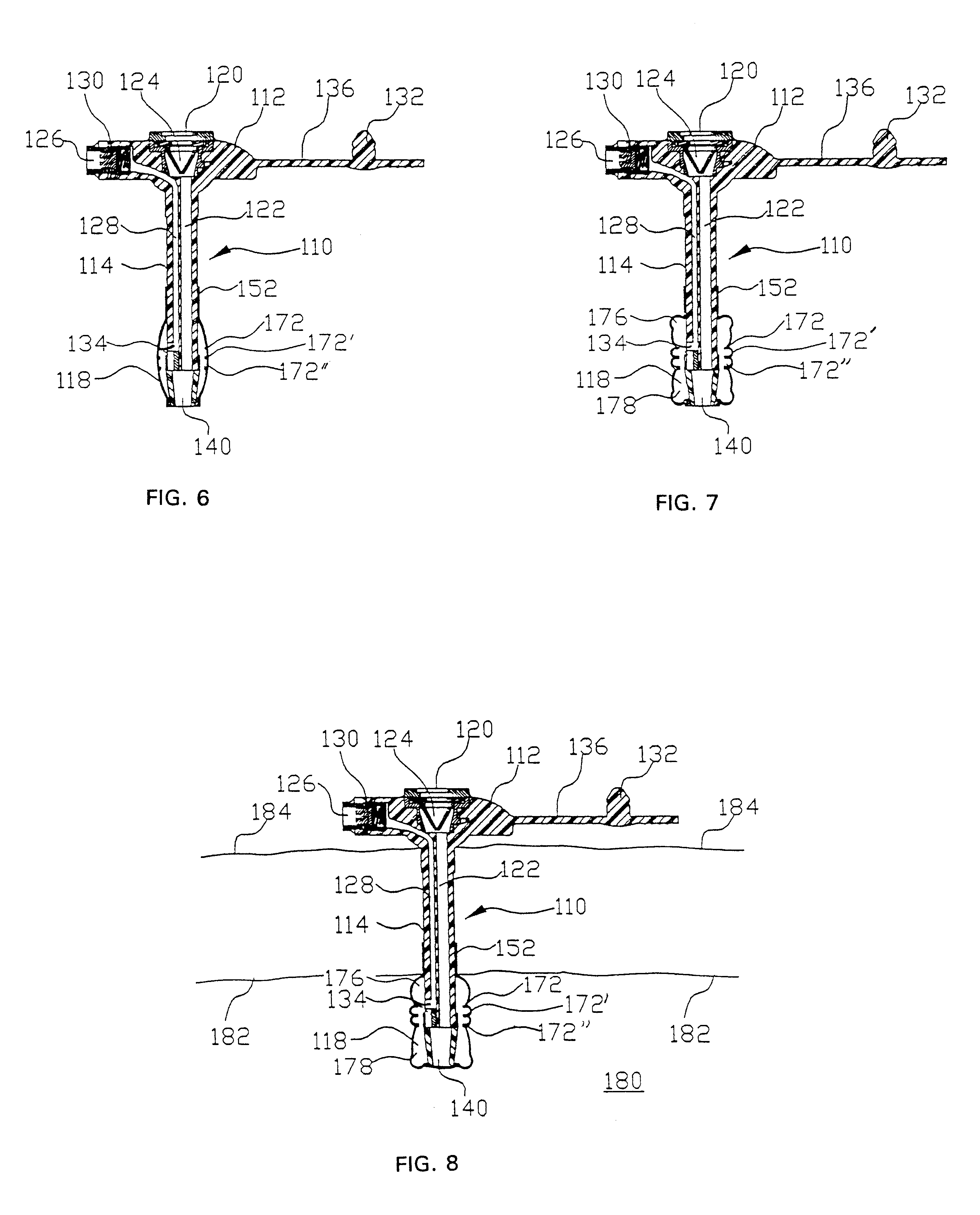
Referring now to FIGS. 1-5, there is shown, generally designated at 10, a balloon catheter. The balloon is comprised primarily of a proximal head 12, a shaft 14 and a balloon 18. The head further comprises a proximal opening 20 to a feeding lumen 22 within the shaft 14, for feeding bolus or other nutrient formula (not depicted) to a patient (not depicted). Disposed between the opening 20 and the lumen 22, is an anti reflux valve 24 to prevent back-flow of the nutrient formula. Inflation port 26 is also disposed in head 12. Inflation port 26 communicates with inflation lumen 28 which extends longitudinally through the shaft 14. The inflation lumen 28 terminates laterally to the shaft 14 at port 34, inside the balloon 18. A releasable one-way fluid valve 30 is disposed between the inflation port 26 and inflation lumen 28. Application of positive fluid pressure such as air o...


PUM


Abstract

A balloon catheter having a balloon disposed upon an elongate shaft near a relatively rigid distal insertion tip, a fluid lumen for fluid communication with a body cavity and an inflation lumen for fluid communication with the balloon. The balloon holds the catheter tip within a body cavity such as the stomach for long-term enteral feeding. The balloon is configured such that upon inflation, the balloon distends distally to cover the distal tip thus insulating it from sensitive anatomy.

Description

1. The Field of the InventionThe present invention relates generally to an apparatus for catheterizing a body cavity, and is particularly directed to a balloon catheter with a distally distending balloon which envelops the catheter tip upon inflation.2. Description of the Related Art and Background of the InventionCatheterizing a body cavity can be advantageous in many instances such as to insert or remove fluids to or from the cavity. It is also known to be desirable to use a device such as an inflated balloon near the tip of the catheter to hold it in the body cavity. This type of balloon is fashioned around the perimeter of the catheter shaft such that when it is deflated, it adds little to the overall diameter of the catheter. When the catheter tip is inside the body cavity, the balloon is inflated and thereby precludes withdrawal of the portion of the catheter distal to and covered by the balloon. Examples of cavities often catheterized in this manner are the stomach or an inte...

Claims


Application Information

Patent Timeline
Patent Type & Authority Patents(United States)
IPC IPC(8): A61J15/00A61M25/02A61M25/04
CPCA61J15/0015A61J15/0042A61M25/04A61J15/0065A61M2025/0233
Inventor WILLIS, ALLAN F.CHRISTIAN, KELLY J.KENOWSKI, MIKE
Owner KIMBERLY-CLARK WORLDWIDE INC
Why Eureka
Try Eureka