Positional deviation correction using different correction values for monochrome and color bi-directional printing

a correction value and correction value technology, applied in the field of image printing, can solve the problems of deviation correction providing little improvement in color image quality, major deviation in the position of printed cyan dots, and deviation correction providing little improvement in the quality of color imag

Inactive Publication Date: 2001-07-31
SEIKO EPSON CORP
View PDF8 Cites 74 Cited by
  • Summary
  • Abstract
  • Description
  • Claims
  • Application Information

AI Technical Summary

Problems solved by technology

A problem that readily arises in bi-directional printing is that of deviation in printing position between forward and reverse printing passes in the main scanning direction caused by backlash in the main scanning drive mechanism and warping of the platen that supports the print media.
As a result, the deviation correction provides little improvement in the quality of the color image.
However, since the composite velocity vector CV.sub.C of cyan ink

Method used


Image

  • Positional deviation correction using different correction values for monochrome and color bi-directional printing
  • Positional deviation correction using different correction values for monochrome and color bi-directional printing
  • Positional deviation correction using different correction values for monochrome and color bi-directional printing

Examples


third embodiment

(3) First Modification of the Third Embodiment

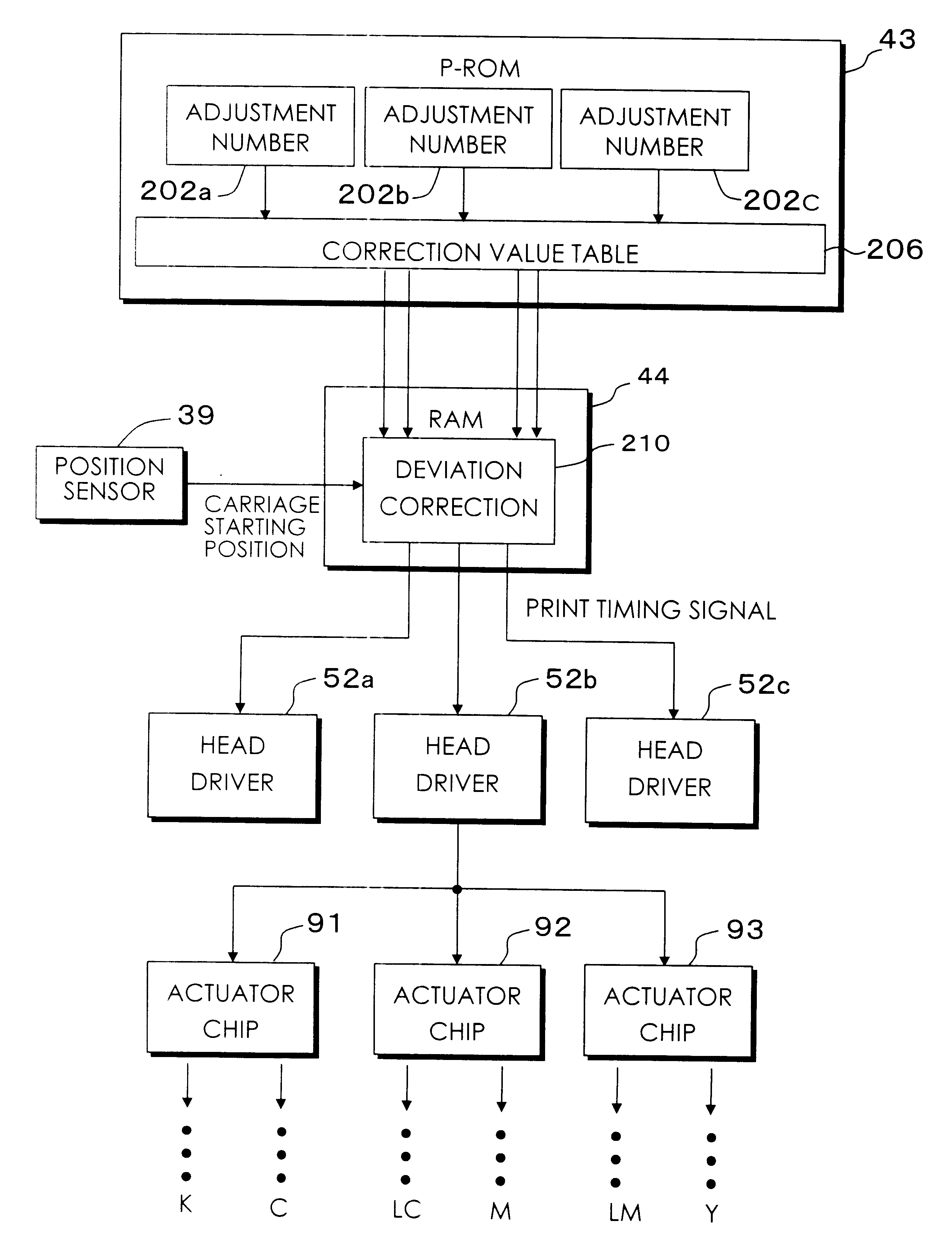
FIG. 27 is a block diagram of the main configuration involved in the correction of deviation during bi-directional printing in the case of a first modification of the third embodiment. The difference compared to the configuration of FIG. 25 is that each of the actuator chips 91, 92 and 93 is provided with its own head drive circuit 52a, 52b and 52c, allowing each actuator chip to be driven independently. Correction of positional deviation during bi-directional printing can therefore also be effected on an actuator chip by chip basis.

(4) Second Modification of the Third Embodiment

FIG. 28 shows a test pattern printed out for determining correction values in a second modification of the third embodiment. In accordance with the third embodiment forward and reverse pass test patterns are printed out in light cyan and light magenta to obtain correction values for each color. However, instead a single test pattern may be printed in light cyan a...

modification 1

F1. Modification 1

With respect to using reference and relative correction values to correct positional deviation during bi-directional, as in the first and second embodiments, when the printer used is able to move the carriage at a plurality of main scanning velocities, relative correction values for the nozzle rows should be set for each such main scanning speed. As in the third embodiment, with respect also to when an absolute correction value is set for each nozzle row, when the printer used is capable of moving the carriage at a plurality of main scanning velocities (speeds), the correction values may be set for each main scanning speed. As can be understood from the explanation made with reference to FIG. 9, changing the main scanning velocity Vs also changes the degree of relative positional deviation between the rows of nozzles. As such, setting a relative correction value for each main scanning speed makes it possible to achieve a further decrease in positional deviation dur...

modification 2

F2. Modification 2

With respect to a multilevel printer which is capable of printing dots of the same color in different sizes, as in the first and second embodiments, it is preferable to set a relative correction value for each dot size. As in the third embodiment, with respect also to when an absolute correction value is set for each nozzle row, when the printer used is capable of printing dots of the same color in different sizes, the correction values may be set for each dot size. Setting a relative correction value for each dot size makes it possible to achieve a further decrease in positional deviation during bi-directional printing. Sometimes a multilevel printer is only able to form dots of the same size in one main scanning pass using one row of nozzles. When this is the case, a dot size is selected for each main scanning pass, so with respect also to the relative correction value used to correct the positional deviation, for each main scanning pass a suitable value is selec...


PUM


Abstract

In monochrome printing mode, a first correction value is set for correcting printing positional deviation between ink droplets printed during forward and reverse main scanning passes. In color printing mode, a second correction value is set for correcting printing positional deviation between ink droplets printed during forward and reverse main scanning passes. An adjustment value is determined for reducing printing positional deviation during forward and reverse main scanning passes. For this, in monochrome printing mode the first correction value is used as an adjustment value, and in color printing mode at least a second correction value is used to determine an adjustment value. Following this, the adjustment value is used to adjust printing positions during forward and reverse main scanning passes.

Description

1. Field of the InventionThis invention relates to a technology for printing images on a print medium using a bi-directional reciprocating movement in a main scanning direction. The invention particularly relates to a technology for correcting printing positional deviation between forward and reverse passes.2. Description of the Related ArtIn recent years color printers that emit colored inks from a print head are coming into widespread use as computer output devices. In recent years, such color printers have been devised as multilevel printers able to print each pixel using a plurality of dots having different sizes. Such printers use relatively small ink droplets to form relatively small dots on a pixel position, and relatively large ink droplets to form relatively large dots on a pixel position. These printers can also print bi-directionally to increase the printing speed.A problem that readily arises in bi-directional printing is that of deviation in printing position between fo...

Claims


Application Information

Patent Timeline
IPC IPC(8): B41J19/14B41J19/20B41J19/00B41J2/21B41J2/51B41J19/18B41J2/01
CPCB41J2/2128B41J2/2135B41J19/145B41J19/202B41J2202/17B41J19/142
Inventor OTSUKI, KOICHIYONEKUBO, SHUJITAYUKI, KAZUSHIGEMITSUZAWA, TOYOHIKO
Owner SEIKO EPSON CORP
Why Eureka
Try Eureka