Method of wheelchair construction

Inactive Publication Date: 2001-08-07
DA INT
View PDF19 Cites 19 Cited by
  • Summary
  • Abstract
  • Description
  • Claims
  • Application Information

AI Technical Summary

Problems solved by technology

Unfortunately, the two above-described designs have one major flaw in common--the strength inconsistencies of the welded joints.
Breakage of welded or brazed joints is the main cause for structural failure in wheelchairs.
Welding or brazing also creates a heat-affected zone weakening the frame tube around the welded or brazed joints and making repairs in most cases impossible.
Repairs and maintenance of these wheelchairs are costly and require elaborate service infrastructure.
In addition, the welded construction makes it extremely difficult, if not impossible,

Method used


Image

  • Method of wheelchair construction
  • Method of wheelchair construction
  • Method of wheelchair construction

Examples


Embodiment Construction

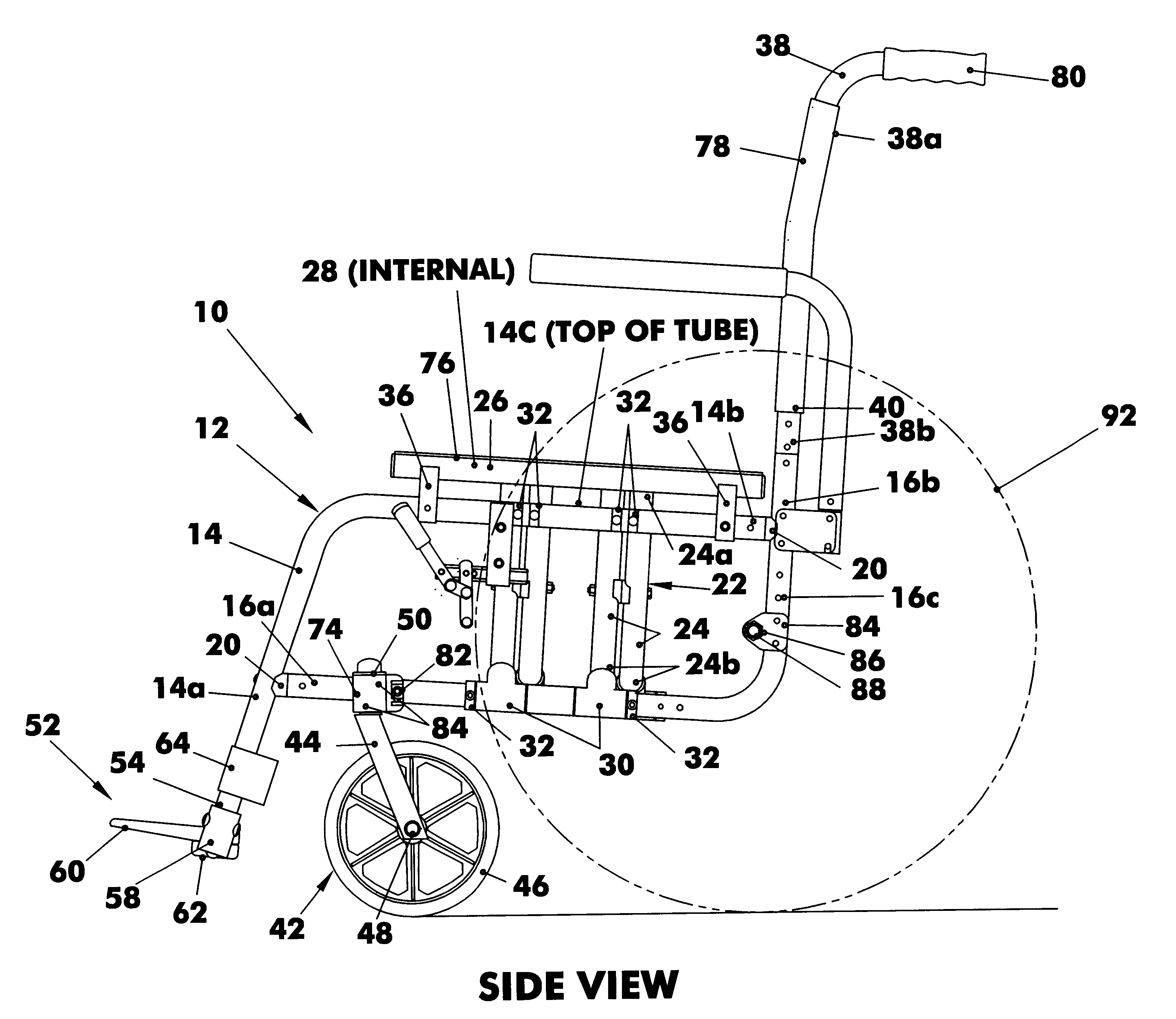
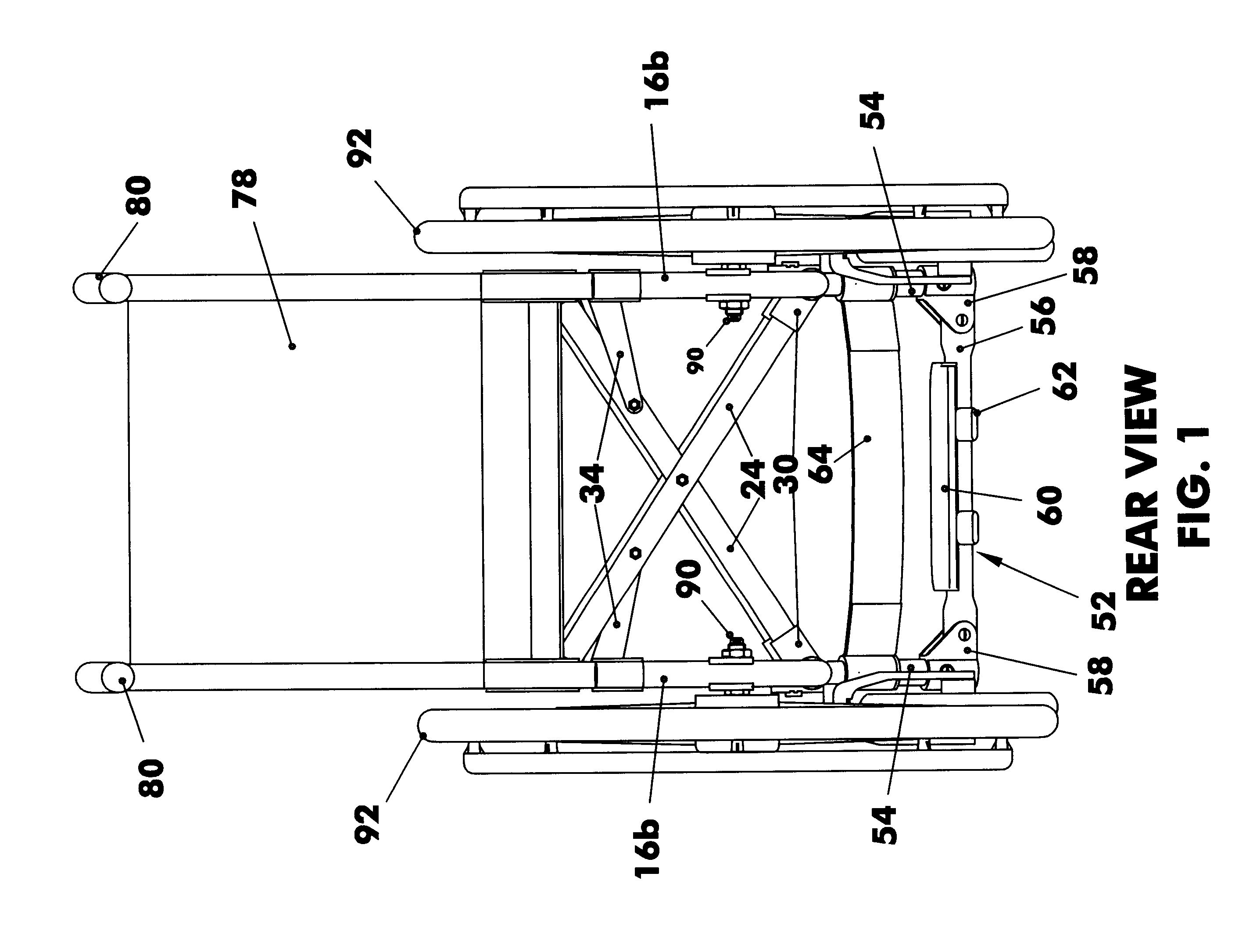
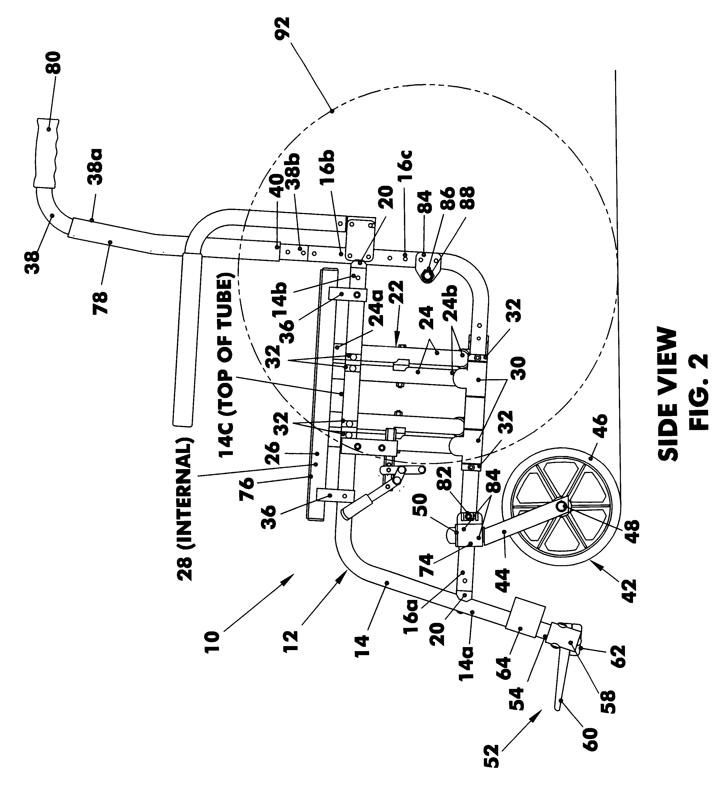
Referring now to the figures, in which identical or similar parts are designated by the same reference numerals throughout, and first referring to FIGS. 1, 2 and 3, a folding wheelchair in accordance with the present invention is generally designated by the reference numeral 10.

The chair 10 has a pair of like side frame assemblies 12 spaced from each other and including a generally horizontal top tube 14 and a generally horizontal bottom tube 16 below the top tube. The top and bottom tubes have front or distal ends 14a, 16a and rear or proximal ends 14b, 16b. An important feature of the invention is that at least one, and usually all, of the tubes that are joined to each other, such as the top and bottom tubes at front ends 14a, 16a, are joined using connector fittings 20. The details of the connector fittings are best shown in FIG. 7 and are more fully described at pages 5, 10 and 17 in U.S. patent application Ser. No. 09 / 442,057, filed simultaneously herewith, for "Distortion-Free...


PUM


Abstract

A method of constructing a wheelchair that is durable, lightweight, economical and fully adaptable to any end user's requirements, such as sizing, convertibility, environment and lifestyle, and the resulting wheelchair, is disclosed, made possible by the utilization of specially designed weld-free connector fittings with any desirable or available tubular materials.

Description

BACKGROUND OF INVENTION1. Field of the InventionThe invention generally relates to wheelchairs, and more specifically to a method of wheelchair construction and resulting wheelchair.2. Description of the Prior ArtThere are two commonly used wheelchair design--the crossbrace folding wheelchair and the welded rigid frame wheelchair. The typical method of construction for both types of wheelchairs is to weld or braze metal tubes together to form frames and folding members. Unfortunately, the two above-described designs have one major flaw in common--the strength inconsistencies of the welded joints. Breakage of welded or brazed joints is the main cause for structural failure in wheelchairs. Welding or brazing also creates a heat-affected zone weakening the frame tube around the welded or brazed joints and making repairs in most cases impossible. Repairs and maintenance of these wheelchairs are costly and require elaborate service infrastructure. In addition, the welded construction mak...

Claims


Application Information

Patent Timeline
IPC IPC(8): A61G5/10A61G5/00A61G5/12A61G5/02A61G5/08
CPCA61G5/00A61G5/023A61G5/025A61G5/026A61G5/027A61G5/1075A61G5/12A61G5/10A61G2005/128A61G2005/0825A61G2005/1051A61G2005/1054A61G5/0825A61G5/1051A61G5/1054A61G5/128
Inventor FRIEDRICH, PAUL
Owner DA INT
Why Eureka
Try Eureka