

Method for adjusting the trigger threshold of vehicle occupant protection devices
- Summary
- Abstract
- Description
- Claims
- Application Information
AI Technical Summary
Benefits of technology
Problems solved by technology
Method used
Image

Examples
Embodiment Construction
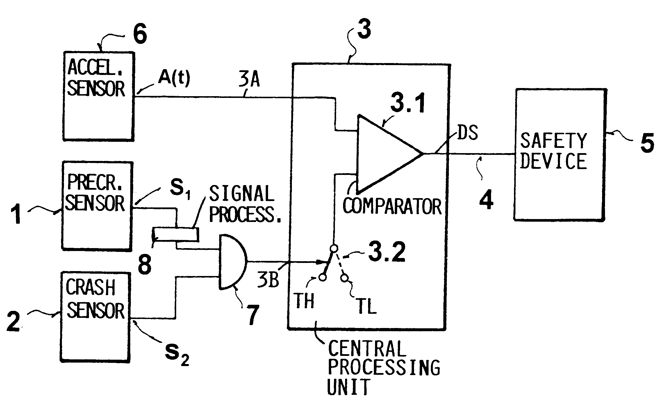
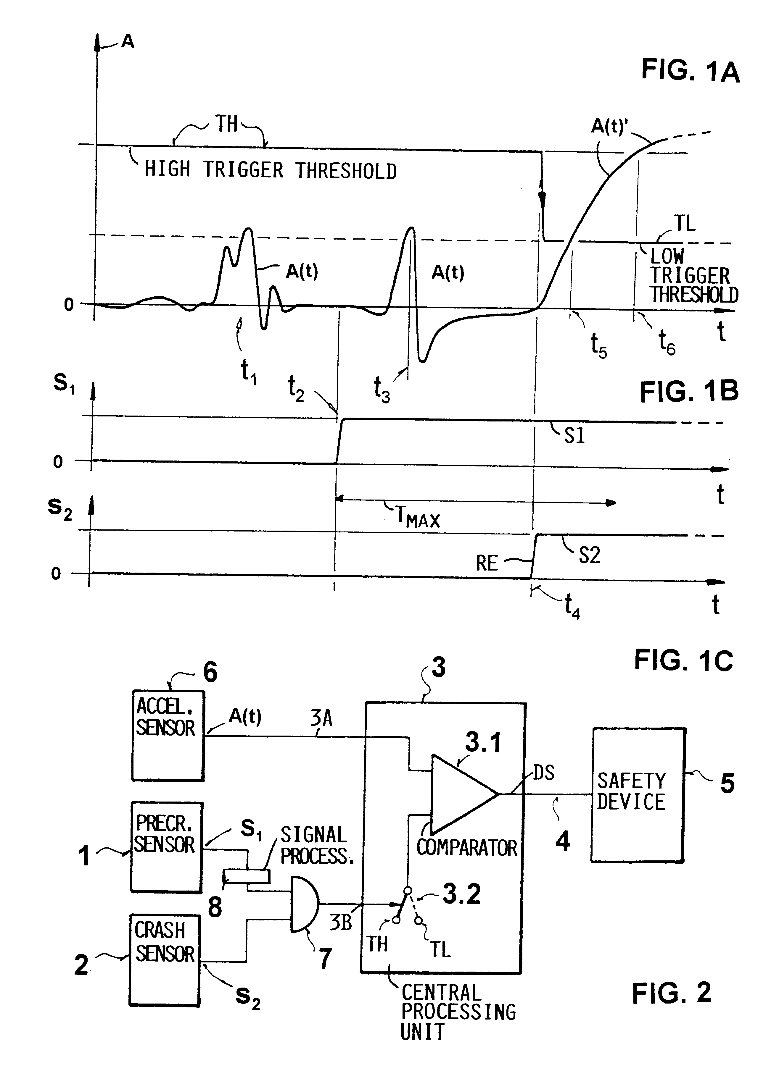
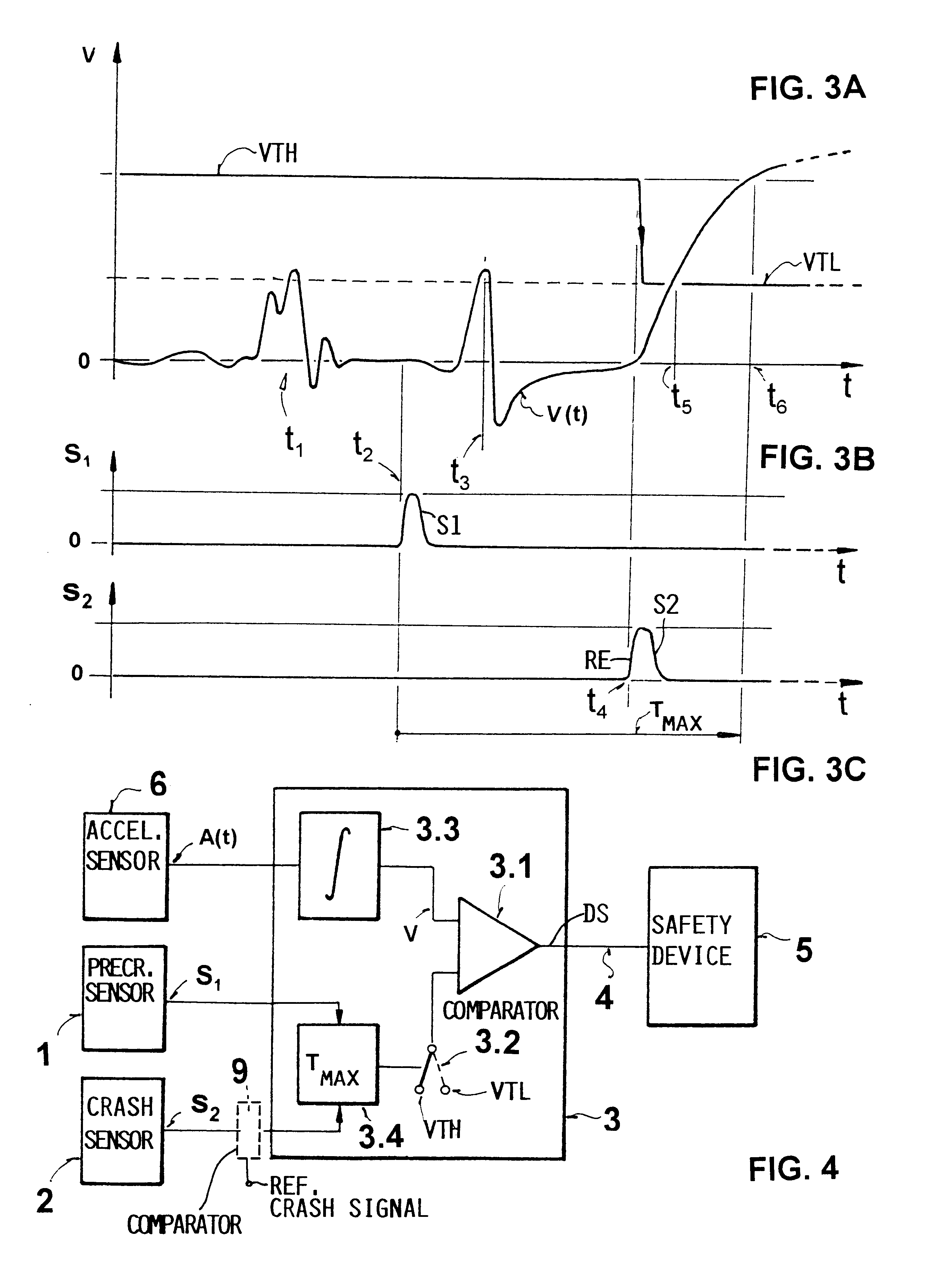
FIGS. 1A to 1B illustrate a possible time sequence for adjusting the trigger threshold. FIG. 1A shows an acceleration signal A(t) changing over time, a high trigger threshold TH, and a low trigger threshold TL. Additionally, and in a time-synchronous fashion, FIGS. 1B and 1C illustrate the precrash signal S1 and the crash signal S2 respectively.
The invention is based on the recognition that in a real emergency a crash signal S2 follows a precrash signal S1 within a time limit T.sub.MAX that can be empirically ascertained. If the crash signal S2 does not occur within this time limit following the precrash signal S1, it is certain that a crash will not occur based on any situation that caused the precrash signal S1.
At a point in time t1, the acceleration signal A(t), which represents, as mentioned, a vehicle motion signal, shows a fault condition which may have been caused, for instance, by vibrations of the vehicle. If the trigger threshold would be permanently kept at the low trigge...
PUM
 Abstract
Description
Claims
Application Information