Method and device for downhole flow rate control

a flow rate control and flow rate technology, applied in the direction of fluid removal, sealing/packing, borehole/well accessories, etc., can solve the problems of sleeve to tilt, tilting torque giving rise to friction between the sleeve and the production tubing, and forming of deposits on the production tubing

Inactive Publication Date: 2001-08-14
SCHLUMBERGER TECH CORP
View PDF10 Cites 87 Cited by
  • Summary
  • Abstract
  • Description
  • Claims
  • Application Information

AI Technical Summary

Problems solved by technology

The thrust force or the traction force exerted on the closure sleeve therefore generates torque which tends to cause the sleeve to tilt.
Such tilting torque gives rise to friction between the sleeve and the production tubing.
That purely mechanical effect is accentuated by the particularly unfavorable conditions that prevail at the bottom of the well, and that generally cause a deposit to form on the production tubing.
That effect due to the deposit combines with the tilting effect due the asymmetrical nature of the mechanism to make it particularly difficult to cause the closure sleeve to move.
Very rapidly, the actuator can become too weak to drive the sleeve, and the mechanism seizes.
The reliability of flow rate control devices designed in that way is thus poor.
Another problem that arises with adjustable flow rate vales of that type concerns their fluid-tightness when they are in the closed state.
Thus, when the valve is caused to open starting from its closed state, the gasket situated frontmost relative to the direction of movement of the sleeve is compressed excessively on the side on which the actuator is situated, whereas it is not compressed sufficiently on the opposite side.
The reverse applies to the gasket situated rearmost, which gasket is subjected to excessive compression on the side opposite from the actuator , while being insufficiently compressed on the side on which the actuator is situated.
The gaskets are therefore subjected to cycles of excessive compression and of insufficient compression, thereby accelerating ageing of said gaskets.
Risks of leakage thus appear rapidly in the regions in which the gaskets are insufficiently compressed while the closure sleeve is moving.
This analysis shows that the current design of adjustable flow rate valves placed down wells is not satisfactory from the point of view of reliability.
Any maintenance on such adjustable flow rate valves is costly (removal and re-insertion of the production tubing), and it results in production being interrupted, which causes the yield of the well to drop.

Method used


Image

  • Method and device for downhole flow rate control
  • Method and device for downhole flow rate control
  • Method and device for downhole flow rate control

Examples


Embodiment Construction

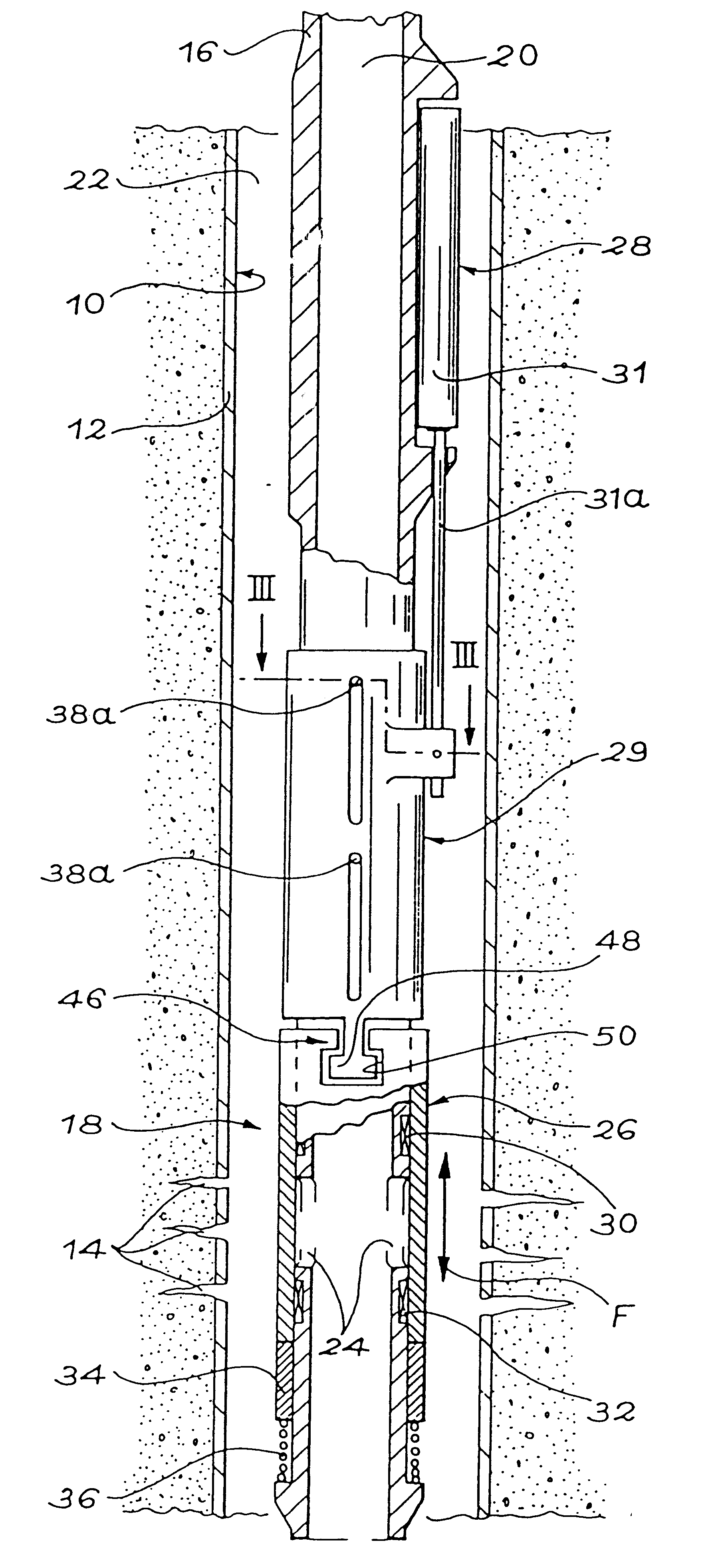
In FIG. 1, reference 10 designates an oil well in production, only a bottom region of which is shown. It should be noted that said bottom region may extend vertically, as shown, or horizontally, or on a slope, without going beyond the ambit of the invention. When the flow rate control device is placed in a horizontal or deviated region of a well, the expressions such as "downwards" and "upwards" used in the following description then mean respectively "away from the surface" and "towards the surface".

The walls of the oil well 10 are reinforced with casing 12. In the region of the well shown in FIG. 1, the casing 12 is perforated at 14 so as to cause the well to communicate with a natural deposit of petroleum fluid (not shown).

To enable the petroleum fluid to be conveyed to the surface, production tubing 16 is received coaxially in the well 10 over its entire depth. The production tubing 16 is made up of a plurality of tubing segments interconnected end-to-end. One of the segments, s...


PUM


Abstract

A flow rate control device (18) placed down an oil well in production comprises holes (24) formed in the production tubing (16), a closure sleeve (26) suitable for sliding facing the holes (24), an actuator (31) disposed eccentrically relative to the tubing (16), and an intermediate part (29). The intermediate part (29) is guided on the tubing (16) in a manner such as to withstand the tilting torque due to the eccentricity of the actuator (31). A coupling (46) that is flexible except in the direction in which the sleeve is moved connects the part (29) to the closure sleeve (26) symmetrically about the axis of the tubing (16). The resulting decoupling guarantees that the sleeve (26) is self-centering, which improves the life-span of the device (18) significantly.

Description

The present invention relates to a method and a device designed to control the downhole flow rate of a petroleum fluid flowing via production tubing.Such a device may, in particular, be used in an oil well in production to optimize the production of the well over time. It is particularly applicable to the case when the petroleum fluid penetrates into a vertical, horizontal, or deviated well at at least two different locations.STATE OF THE ARTIt is known that adjustable flow rate valves can be placed down a well in production, in particular in order to optimize production when the petroleum fluid flows into the well at at least two spaced-apart locations. Documents GB-A-2 314 866 and WO-A-97 / 37102 relate to such adjustable flow rate valves.Adjustable flow rate valves are installed on the production tubing so as to define a passage of adjustable section between the inside of the tubing and the annular space surrounding it. Such a valve commonly comprises a slidably-mounted closure sle...

Claims


Application Information

Patent Timeline
Patent Type & Authority Patents(United States)
IPC IPC(8): E21B34/00E21B34/06
CPCE21B34/066
Inventor HIRON, STEPHANETOURILLON, VINCENTRAYSSIGUIER, CHRISTOPHE
Owner SCHLUMBERGER TECH CORP
Why Eureka
Try Eureka