

Light guide plate, surface light source using the light guide plate, and liquid crystal display using the surface light source
a technology of light guide plate and surface light source, which is applied in the direction of lighting application, light source combination, instruments, etc., can solve the problems of reducing the efficiency of collecting outer light and unable to achieve the effect of reducing power consumption
- Summary
- Abstract
- Description
- Claims
- Application Information
AI Technical Summary
Problems solved by technology
Method used
Image


Examples
first embodiment
the present invention will be described in detail with reference to the drawings.
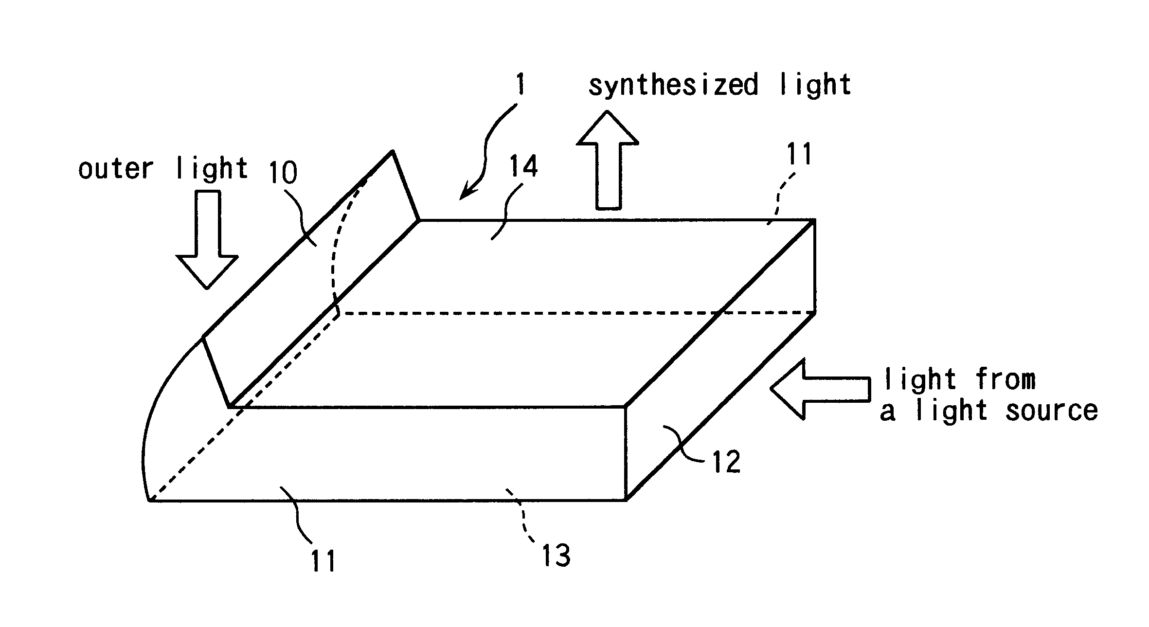
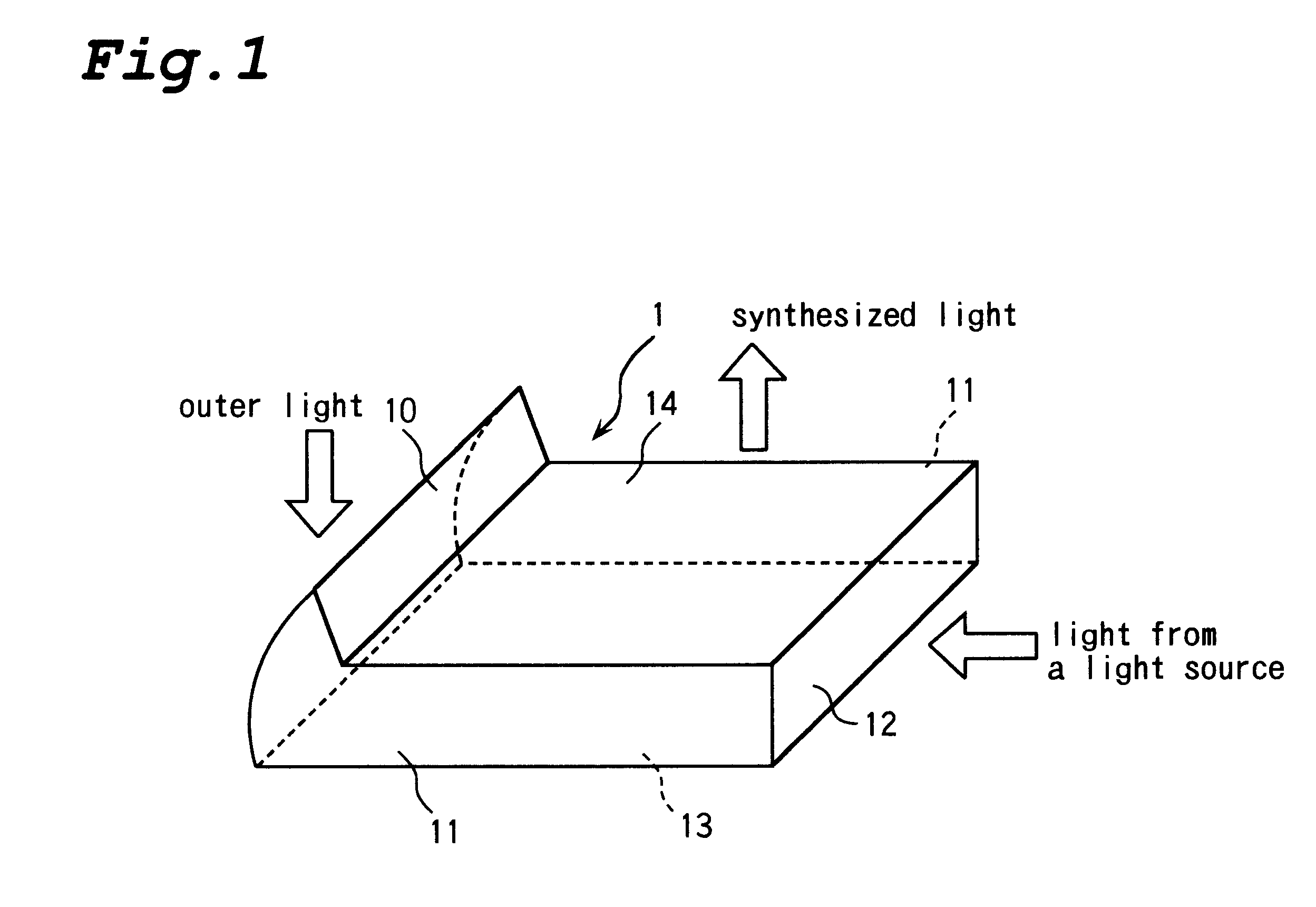
FIG. 1 is a perspective view showing a light guide plate according to a first embodiment.
As for a light guide plate 1, when a body of a light guide plate 1 is formed by resin forming with a mold, an outer light collecting portion 10, which will be described later, is also formed at the same time.
The outer light collecting portion 10 collects outer light such as the sunlight and light from a lighting apparatus as a secondary light. The outer light collecting portion 10 is formed so as to stick out of a light emission surface 14, which will be described later, to the direction to which synthesized light emits (that is, the upper direction in the figure). Accordingly, the surface area of an outer light collecting surface is larger than that of a conventional light guide plate.
As for a light incidence surface 12, described as follow, light, irradiated from a light source (not shown) provided so as to be adj...
second embodiment
the present invention will be described in detail with reference to the drawings.
FIG. 5 is a perspective view showing a light guide plate according to a second embodiment of the present invention.
As for a light guide plate 1 of a second embodiment as well as a first embodiment, when a body of a light guide plate 1 is formed by resin forming with a mold, an outer light collecting portion 10a is also formed at the side end of the light guide plate 1 at the same time. The light guide plate 1 of the second embodiment has the same construction as that of the light guide plate 1 of the first embodiment except for the outer light collecting portion 10a. So the reference numerals are affixed for the same parts, and the explanation is omitted for avoiding duplication of the description.
The outer light collecting portion 10a sticks out of a light emission surface 14 and a light reflection surface 13, which will be described later, to the upper and lower direction of the figure. So an area of ...
third embodiment
the present invention will be described in detail with reference to the drawings.
FIG. 9 is a perspective view showing a light guide plate according to a third embodiment.
As for a light guide plate 1 of a third embodiment as well as a first embodiment, when a body of the light guide plate 1 is formed by resin forming with a mold, an outer light collecting portion 10b is also formed at the side end of the light guide plate 1 at the same time. The light guide plate 1 of the third embodiment has the same construction as that of the light guide plate 1 of the first embodiment except for the outer light collecting portion 10b. So the same reference numerals are affixed for the same parts, and the explanation is omitted for avoiding duplication of the description.
The outer light collecting portion 10b consists of a cylindrical lens having a semicircle shape in cross section, and the surface for collecting outer light (the face formed by sliding the dotted line A-A' to the another side surf...
PUM
 Abstract
Description
Claims
Application Information