Subsea gas separation system and method for offshore drilling

Inactive Publication Date: 2001-08-21
SHELL OFFSHORE
View PDF32 Cites 138 Cited by
  • Summary
  • Abstract
  • Description
  • Claims
  • Application Information

AI Technical Summary

Problems solved by technology

However, the durability and dependability of such a mud circulation system is suspect in the offshore environment and particularly so in light of the incompatibility of the fluid with pumping operations following a well control event.

Method used


Image

  • Subsea gas separation system and method for offshore drilling
  • Subsea gas separation system and method for offshore drilling
  • Subsea gas separation system and method for offshore drilling

Examples


Embodiment Construction

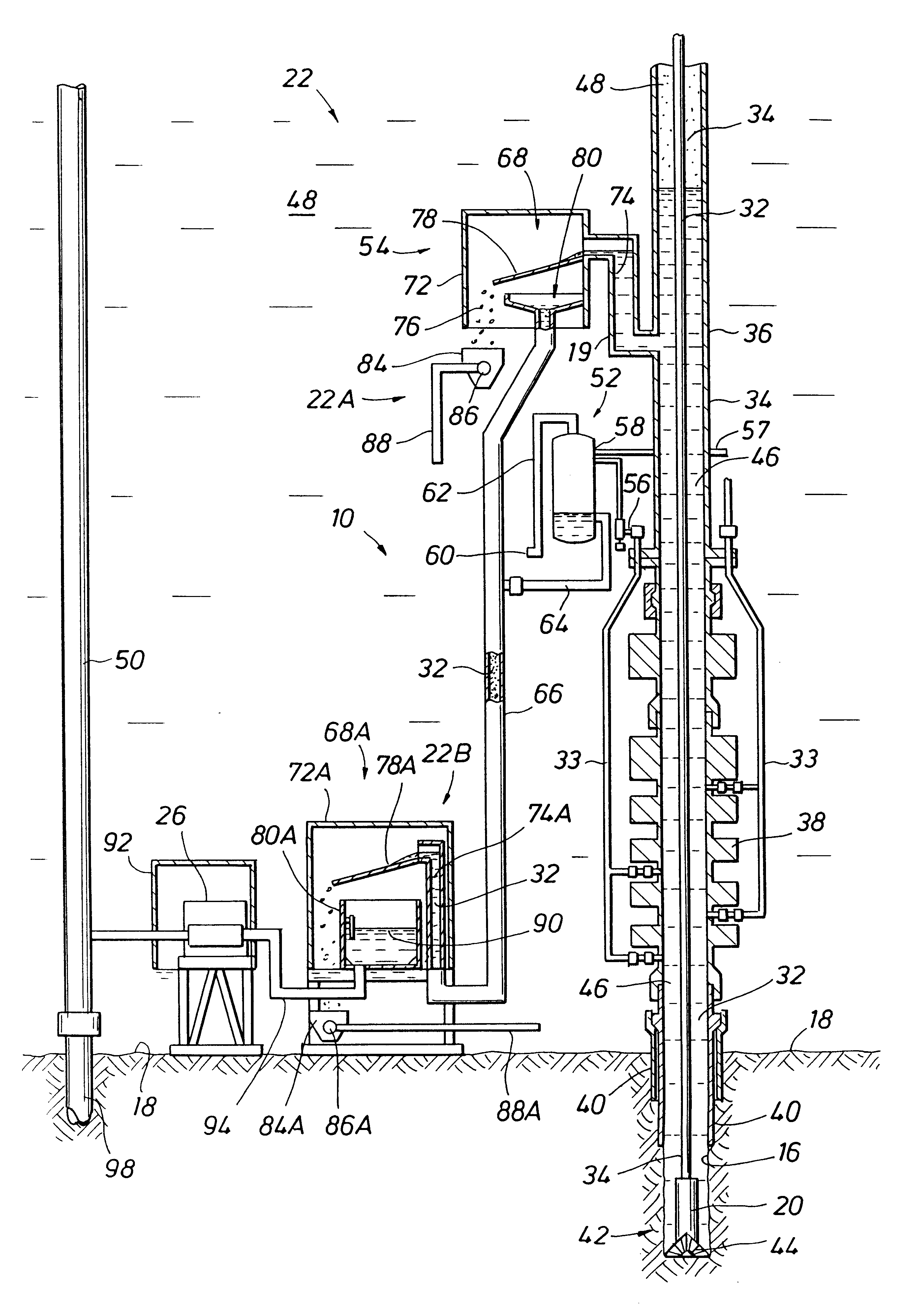
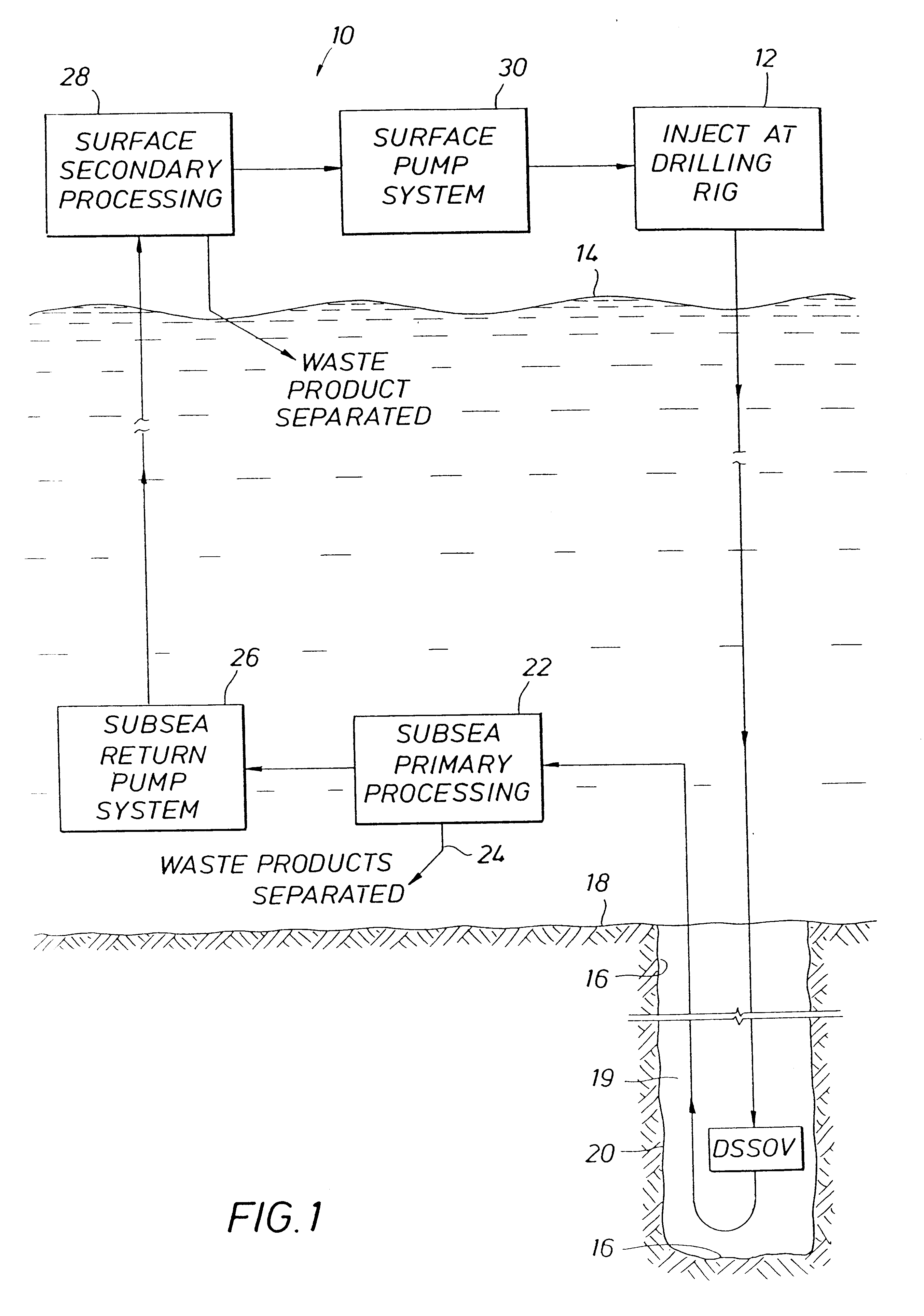
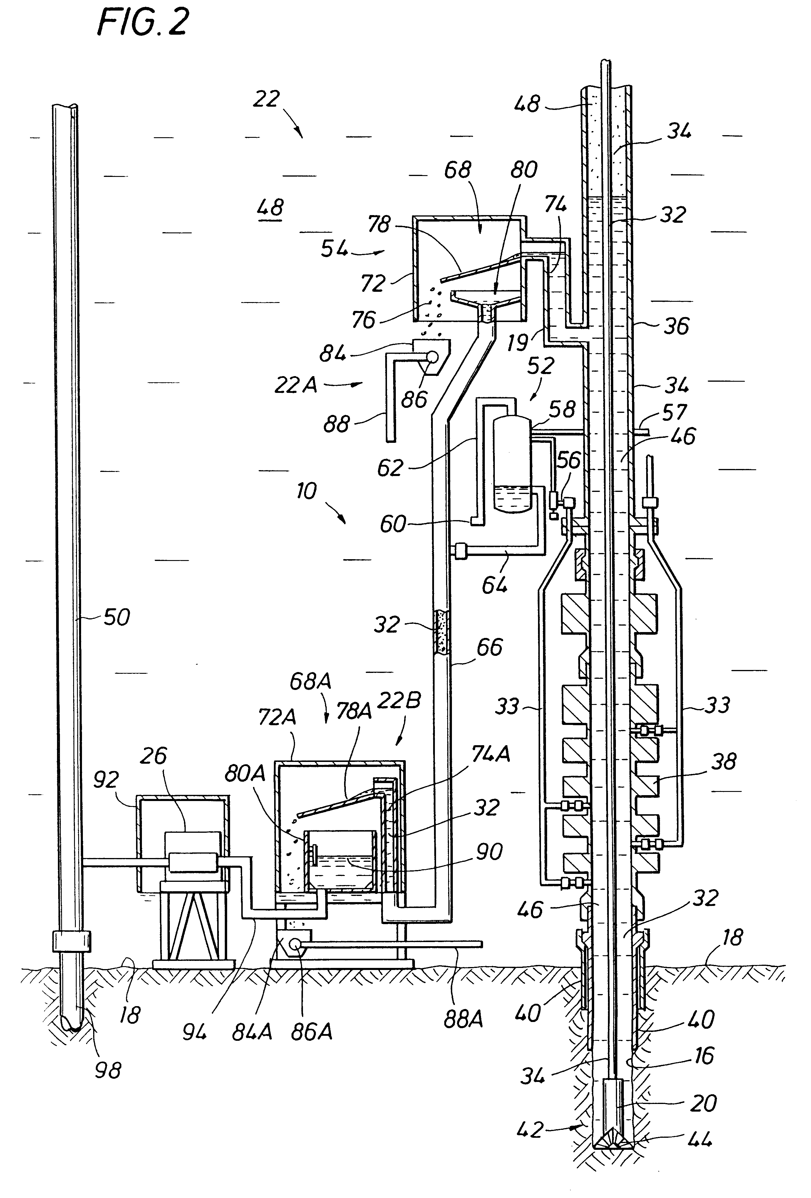
FIG. 1 illustrates schematically one embodiment of a drilling fluid circulation system 10 in accordance with the present invention. Drilling fluid is injected into the drill string at the drilling rig facilities 12 above ocean surface 14. The drilling fluid is transported down a drill string (see FIG. 2), through the ocean and down borehole 16 below mudline 18. Near the lower end of the drill string the drilling fluid passes through a drill string shut-off valve ("DSSOV") 20 and is expelled from the drill string through the drill bit (refer again to FIG. 2). The drilling fluid scours the bottom of borehole 16, entraining cuttings, and returns to mud line 18 in annulus 19. Here, near the ocean floor, the drilling mud is carried to a subsea primary processing facility 22 where waste products, see line 24, are separated from the drilling fluid. These waste products include at least the coarse cuttings entrained in the drilling fluid. With these waste products 24 separated at facilities...


PUM


Abstract

A subsea gas separation system use in drilling an offshore well includes a subsea blowout preventor connected to the well and a gas separator connected to the blowout preventor near the seafloor. Gas released into the well bore during a well control event is removed at the separator and not returned with the drilling mud recirculated to the surface. A method offshore drilling includes a mud circulation circuit established leading down the drill string, through the drill bit, up the borehole, through a subsea pump, and to the surface through a return riser. The subsea pump is protected during critical well control events by removing gas released into the mud at a gas separator located upstream of the subsea pump and in communication with the blowout preventor.

Description

The present invention relates to drilling systems and operations. More particularly, the present invention is a method and system for handling formation fluids entering the wellbore in the form of a hydrocarbon gas during well events.Drilling fluids, also known as muds, cool the drill bit, flush the cuttings away from the bit's formation interface and then out of the system, and stabilize the borehole with a "filter cake" until newly drilled sections are cased. The drilling fluid also performs a crucial well control function and is monitored and adjusted to maintain a pressure with a hydrostatic head in uncased sections of the borehole that prevents the undesired flow of pressured well fluids into the borehole from the formation during drilling operations, i.e., well control events.Conventional offshore drilling circulates drilling fluids down the drill string and returns the drilling fluids with entrained cuttings through an annulus between the drill string and the casing below the...

Claims


Application Information

Patent Timeline
Patent Type & Authority Patents(United States)
IPC IPC(8): E21B21/06E21B21/00E21B33/03E21B33/035
CPCE21B21/001E21B21/06E21B43/36E21B33/035E21B21/067
Inventor GONZALEZ, ROMULO
Owner SHELL OFFSHORE
Why Eureka
Try Eureka