Light transmission tubes

a technology of light transmission tube and light transmission tube, which is applied in the direction of waveguides, lighting and heating apparatuses, instruments, etc., can solve the problems of difficult manufacturing of light transmission tubes in the above manner, electric shock or electric leakage, and low brightness of the circumferential surface area of light transmission tubes, so as to reduce possible light loss, high brightness, and directivity

Inactive Publication Date: 2001-08-21
BRIDGESTONE CORP
View PDF6 Cites 86 Cited by
  • Summary
  • Abstract
  • Description
  • Claims
  • Application Information

AI Technical Summary

Benefits of technology

Further, if the above reflecting layer is formed of light scattering particles such as silicon resin particles, polystyrene resin particles or metal oxide particles, it is possible to effect a light emission having an extremely high brightness and a higher directivity.
Moreover, if a metal sheet or a reflective coating layer containing dispersed light scattering particles is formed on the outer surface of the clad to cover the reflecting layer formed between the clad and core section, it is allowed to remarkably reduce a possible light loss. In this way, even if there is a defect such as a pin hole formed in the reflecting layer, a light leaking through such pin hole to the back surface of the reflecting layer, or a light leaking from the lateral direction, will all be reflected by the metal sheet or the reflective coating layer, thereby ensuring a higher brightness on one side of the light transmission tube opposite to the reflecting layer side.

Problems solved by technology

As a result, a brightness on the circumferential surface area of the light transmission tube is usually not very high.
However, if a light transmission tube has a structure which is formed by filling the internal space of the tubular clad with a liquid state polymerizable monomer (for forming the core section), followed by applying a pressure to effect a predetermined polymerization of the monomer, the formation of the irregular convex and concave portions on the internal surface of the clad will cause the clad to be easily broken, hence making it difficult to manufacture a light transmission tube in the above manner.
However, when using a neon tube or a fluorescent tube, since a high voltage is needed to be applied to a neon tube or a fluorescent tube, there is a danger that an electric shock or an electric leakage may happen.
As a result, such a neon tube or a fluorescent tube can not be used under water, nor is it suitable for them to be used in a place where rain water or snow frequently enters.
Further, since a neon tube or a fluorescent tube has been formed into a tubular shape, they do not have a desired impact resistance.
However, since in use of such a light transmission tube, a light will be caused to emit from the circumferential surface area of the tube in every direction along the cross sectional plane, it is impossible to obtain a light emission having a sufficiently high brightness in a predetermined desired direction.
But, a problem with such a light directing rod is that if some dust or small rubbish is attached to the outer circumferential surface of the light directing rod, such dust or small rubbish will cause a deterioration in the light transmissibility of the transparent rod.
As a result, a desired brightness will be decreased and / or a brightness distribution in the longitudinal direction of the transparent rod will have an undesired variation.
Because of this, such a light directing transparent rod can only be used in a very clean environment free of dust or small rubbish.
In fact, since a relatively long time is required in a subsequent drying process for drying the printed coating material, and since the whole manufacturing process has to involve at least two steps including rod formation and coating material printing, an industrial productivity is low and its manufacturing cost is high.
In addition, since the above printing process is performed on a rod-like member, a desired reflective layer can only be formed on one side of the outer circumferential surface thereof, hence undesirably causing an emitted light to receive a restriction in its emitting direction.
As may be understood from the above discussion, in any of the related prior art techniques, there has not been provided a light transmission tube whose brightness may be increased by emitting a light from a circumferential surface of said tube in a specifically determined direction, which light transmission tube is capable of being used without a problem that its light emitting performance will be possibly deteriorated because of an attachment of dust or small rubbish thereto.

Method used


Image

  • Light transmission tubes
  • Light transmission tubes
  • Light transmission tubes

Examples


example 1

60 parts by weight of MMA (methyl methacrylic acid), 40 parts by weight of LMA (lauryl methacrylic acid), and 0.05 parts by weight of BPO (benzol peroxide) were mixed together to form a monomer solution (a liquid material for forming the core section 2, having a specific gravity of 0.92). Then, 0.15 parts by weight of light scatterring particles, which may be silicon resin particles (made by Toshiba Silicon Co., Ltd.) having an average particle size of 7 .mu.m and a specific gravity of 0.92, or may be polystyrene resin particles (made by Sekisui Chemical Products Co., Ltd.) having an average particle size of 10 .mu.m and a specific gravity of 1.06, were added into 100 parts by weight of the monomer solution. Afterwards, the monomer solution containing the light scatterring particles was poured into an FEP tube having an outer diameter of 6 mm and a length of 1.5 m. Subsequently, both ends of the FEP tube were sealed up and the tube itself was kept still in a horizontal position for ...

example 2

A light transmission tube was manufactured in the same manner as in Example 1. The brightness on one side surface area of the light transmission tube obtained in Example 2 was measured in the same manner as in Example 1, with the use of an LED red lamp as a light source (an applied voltage was 2 V, an electric current was 20 mA, an electric power was 0.04 W). The light transmission tube obtained in Example 2 was compared with another light transmission tube (Comparative Example 2) which involves the use of a light reflective tape (consisting of a polyvinyl chloride resin containing a white color pigment, the tape itself being coated with an adhesive agent) bonded on the outer surface of the clad so as to cover the reflecting layer. The results of the measurements of the two light transmission tubes are shown in the following Table 2.

It is understood from the above Table 2 that the light transmission tube obtained in Example 2 has a high brightness on one side surface area thereof, a...

example 3

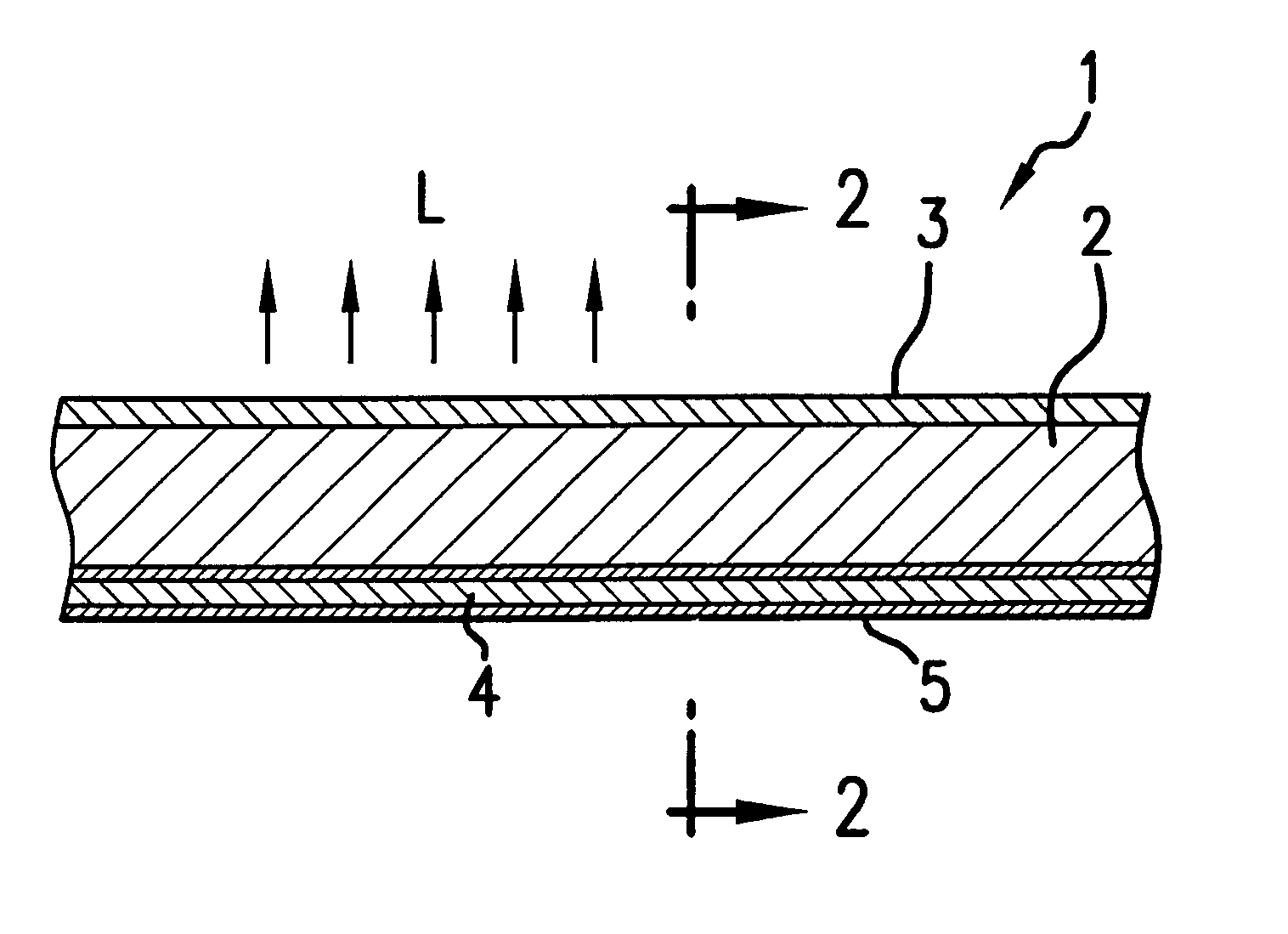
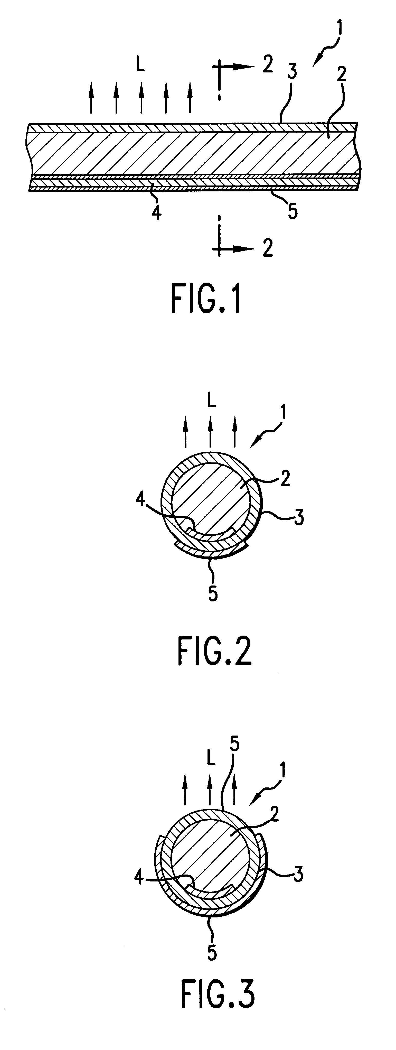
A three-material extrusion molding machine having three crew sections was used, which is capable of extruding at the same time a core formation material, a clad formation material and a light reflecting material. The core formation material, the clad formation material consisting of an acryl polymer, a reflecting layer formation material obtained by dispersing fifteen weight percent of titan oxide in an acryl polymer (which is the same as the acryl polymer for forming the clad), are at the same time introduced into an inlet mouth adaptor on the three-material extrusion molding machine, thereby simultaneously forming a solid cylindrical rod having a diameter of 6 mm, a belt-like white color reflecting layer having a width of 1.5 mm and a thickness of 0.01-0.02 mm (which is formed on the outer surface of the solid cylindrical rod), and a tubular clad coverring the rod and the reflecting layer, thus producing a cylindrical light transmission tube. The brightness on one side surface are...


PUM


Abstract

A light transmission tube includes a tubular clad and a core section having a higher refractive index than that of the tubular clad. A belt-like reflecting layer is formed between the tubular clad and the core section, extending in the longitudinal direction of the tubular clad, in a manner such that a light passing through the core section is reflected and scatterred by the reflecting layer and then emitted from an outer surface area of the tubular clad, which outer surface area is located opposite to one side of the tubular clad where the reflecting layer has been formed. Further, the reflecting layer may be so formed that a light is allowed to be emitted in a plurality of directions. Moreover, the belt-like reflecting layer may be formed into a spiral configuration. The width of the belt-like reflecting layer may be changed in the longitudinal direction of the light transmission tube. The tubular clad is allowed to have a non-circular cross section. The clad formation material may contain an ultraviolet light shielding material or an ultraviolet light absorbing material.

Description

BACKGROUND OF THE INVENTION AND RELATED ART STATEMENTThe present invention relates to light transmission tubes. Each of the light transmission tubes to which the present invention relates is comprised of a transparent tubular clad and a transparent core section having a higher refractive index than the transparent tubular clad. In particular, this invention relates to light transmission tubes each of which is capable of emitting a light having a predetermined directivity from one side of the clad (a part of its outer surface area).In general, if a light transmission tube is comprised of a tubular clad and a core section having a higher refractive index than the tubular clad, a usually adopted method for the use of it is that a large amount of light be sent toward the front end of the light transmission tube. As a result, a brightness on the circumferential surface area of the light transmission tube is usually not very high. As a method for increasing the above brightness, it is all...

Claims


Application Information

Patent Timeline
Patent Type & Authority Patents(United States)
IPC IPC(8): F21V8/00G02B6/02G02B6/032G02B6/00
CPCG02B6/001G02B6/032G02B6/0096G02B6/0001Y10S385/901
Inventor SUGIYAMA, HIDEOSUGIMACHI, MASATOISHIHARADA, MINORUMORIMURA, YASUHIROTERAHAMA, TATSUOFUKUYAMA, HIROSHITANUMA, ITSUO
Owner BRIDGESTONE CORP
Why Eureka
Try Eureka