Apparatus for calibrating hardness tester, method for calibrating the same and apparatus for evaluating dynamic characteristic of specimen

a technology of hardness tester and test instrument, which is applied in the field of apparatus for calibrating hardness tester, method for calibrating apparatus and hardness tester, and apparatus for evaluating dynamic characteristics of specimens, can solve problems such as inability to carry out dynamic tests

Inactive Publication Date: 2001-08-28
MITUTOYO CORP
View PDF3 Cites 13 Cited by
  • Summary
  • Abstract
  • Description
  • Claims
  • Application Information

AI Technical Summary

Problems solved by technology

However, according to a conventional hardness tester, it is not possible to carry out the dynamic test but to carry out only the static test.
Therefore

Method used


Image

  • Apparatus for calibrating hardness tester, method for calibrating the same and apparatus for evaluating dynamic characteristic of specimen
  • Apparatus for calibrating hardness tester, method for calibrating the same and apparatus for evaluating dynamic characteristic of specimen
  • Apparatus for calibrating hardness tester, method for calibrating the same and apparatus for evaluating dynamic characteristic of specimen

Examples


first embodiment

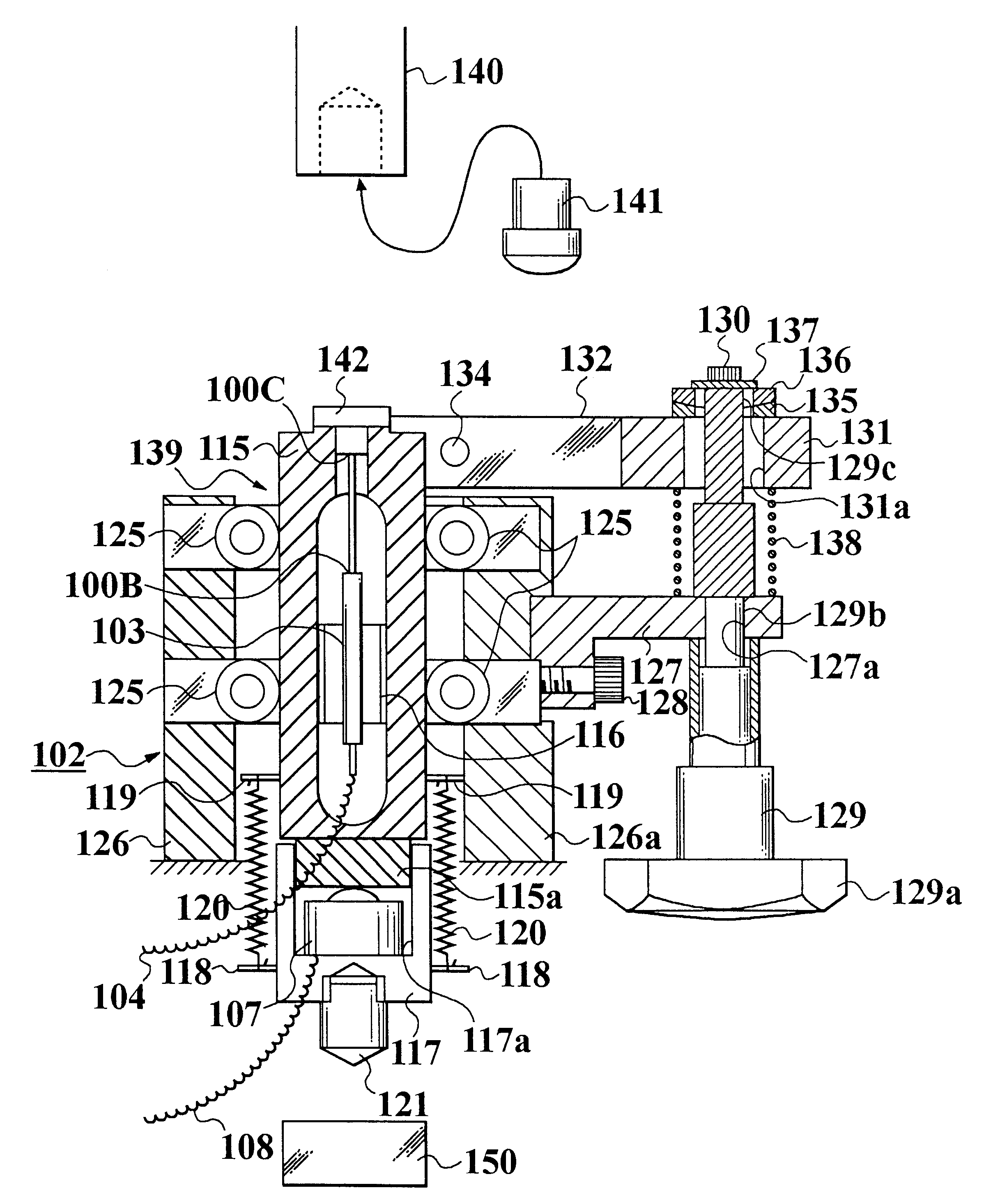
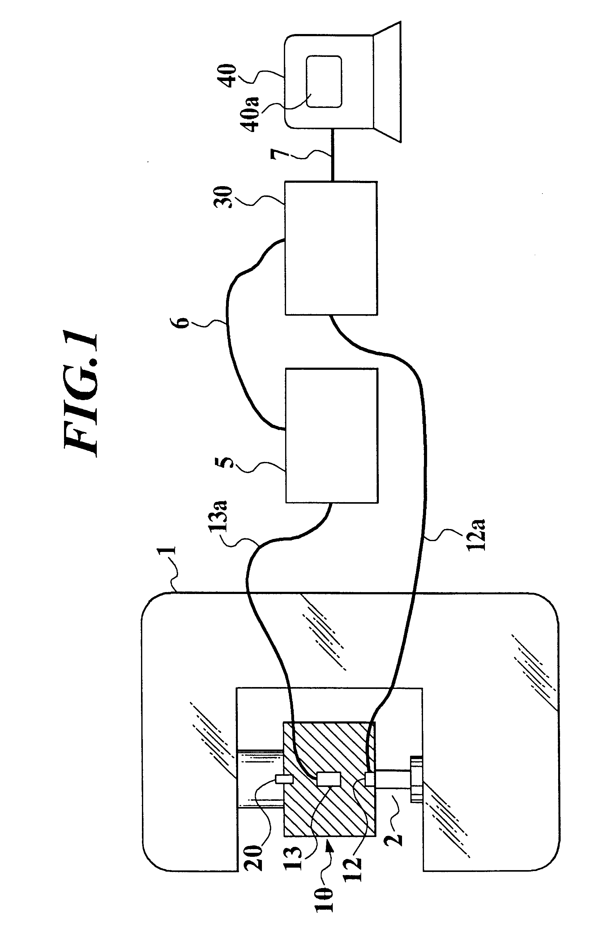
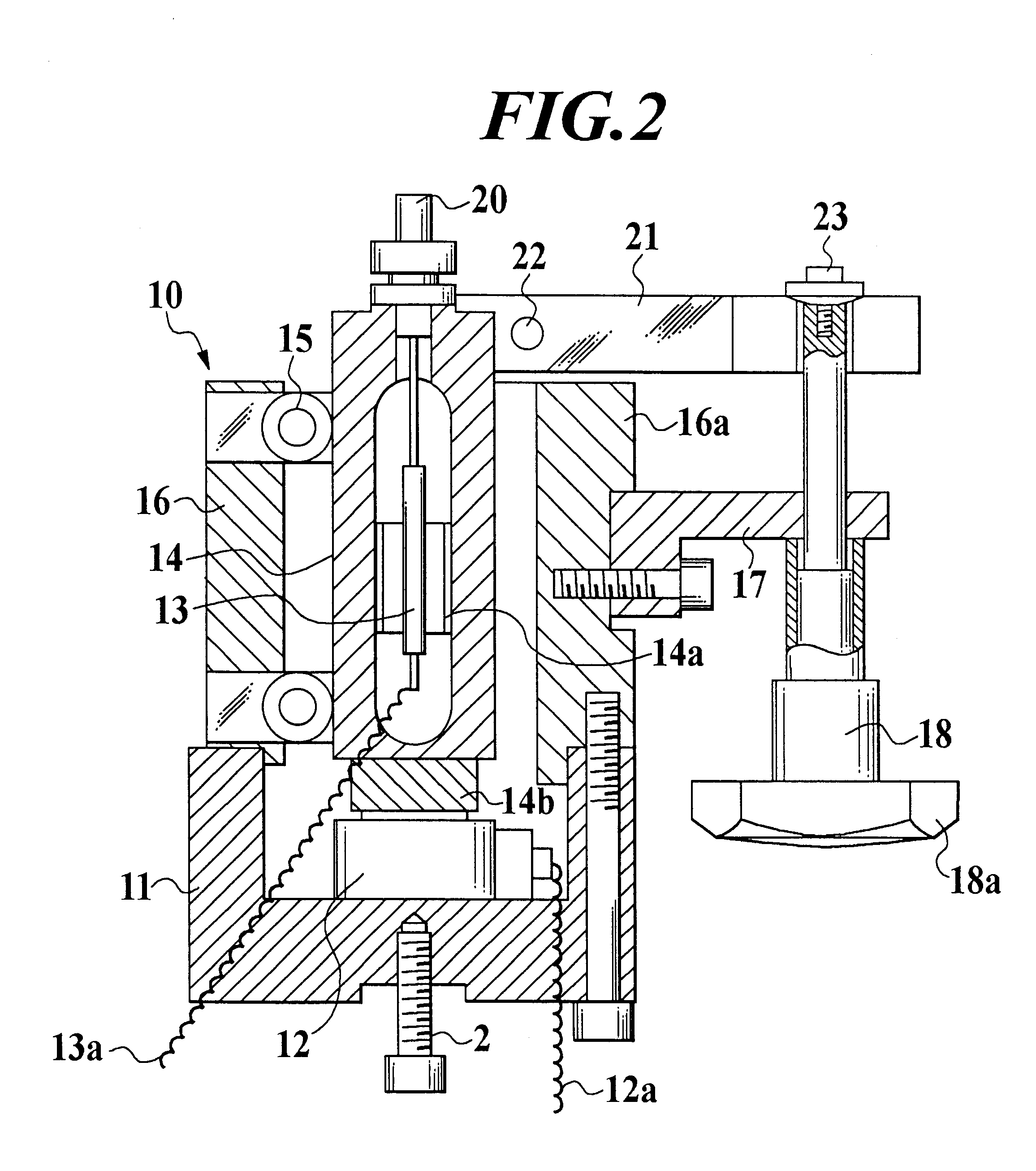
Referring now to FIGS. 1 to 8B, the calibration apparatus for the Rockwell hardness tester and the calibration unit thereof according to the present invention will be described as follows. FIG. 1 is a schematic illustration of whole constitution of the calibration apparatus; FIG. 2 is a vertical cross-sectional view of the calibration unit; FIG. 3 is a plan view thereof; FIGS. 4 and 5 are partial front views thereof; FIG. 6 is a schematic illustration explaining the calibration by the calibration apparatus; FIG. 7 is a graph displayed on a display portion of the calibration apparatus; FIG. 8A is an enlarged view showing a portion indicated by an arrow P shown in FIG. 7 when the calibration is incorrect; and FIG. 8B is an enlarged view showing a portion indicated by an arrow Q shown in FIG. 7 when the calibration is incorrect.

In FIG. 1, reference numeral 1 denotes the Rockwell hardness tester, therefrom an anvil and an indenter are removed and the calibration unit 10 is installed to ...

third embodiment

In the third embodiment, the calibration for the load cell 12 which is mounted to the calibration unit 10 of the calibration apparatus shown in FIG. 1, that is, the calibration for the calibration apparatus is carried out as follows.

The calibration unit 10 is installed to the tester 1, the portion of which is obtained by removing the anvil and indenter from the tester 1, in the same way as the first embodiment.

Then, test forces are applied to the load cell 12 of the tester 1. In the third embodiment, as shown in FIG. 10, a rating force of M.sub.max (kN) is divided into ten forces of M.sub.0, M.sub.1, M.sub.2, M.sub.3, . . . , and M.sub.10 (=M.sub.max kN), which have the same intervals between them, and the forces as the test forces are applied to the load cell 12 in order. Each output power e.sub.1, e.sub.2, e.sub.3, . . . , e.sub.10 (mV / V) of the load cell 12 according to the test forces is input in the micro computer 40 through the data recorder 30. A relation between the test for...

second embodiment

The calibration for the commercial hardness tester is performed in the same way as the second embodiment by employing the calibration apparatus of which load cell is calibrated as above-described.

After the calibration unit 10 is installed to the commercial hardness tester, the tester is operated in the same way as the hardness test, test forces of ni including no-load are applied to the load cell 12. The test forces of n.sub.i are displayed on the display portion 40a. The outputs of the load cell 12 in the time are memorized in the computer 40. The actual test forces of M. working to the tester are calculated according to the outputs(mV / V) of the load cell 12 and the equation [math 2] by the computer 40, and a function of n.sub.i =f(M.sub.i) is calculated. This is the characteristic of the tester to be calibrated. The function of n.sub.1 =f(M.sub.1) is input in the micro computer 40.

As above-described, it is possible to easily install the calibration unit to the commercial hardness ...


PUM


Abstract

A method for calibrating an apparatus for calibrating a hardness tester, the method comprising the steps of: setting a plurality of calibration points between a rated force point at which a rated force of a force measuring member is applied and a zero point at which no-load is applied, for measuring outputs (mV/V) from the force measuring member according to test forces(N) applied to the force measuring member; and calculating a relation between the test forces(N) and the outputs(mV/V) as an approximation based on the test forces(N) and the outputs(mV/V) according to the test forces(N) at the calibration points. An apparatus for evaluating a dynamic characteristic of a specimen, which installed in a hardness tester, the apparatus comprising: a force measuring member; a force transmitting portion which is movable up and down; a distance measuring member incorporated in the force transmitting portion to be contacted with the force measuring member from above; and an indenter.

Description

1. Field of the InventionThe present invention relates to an apparatus for calibrating a hardness tester, a method for calibrating the apparatus and a hardness tester and an apparatus for evaluating a dynamic characteristic of a specimen.2. Description of Related ArtGenerally, hardness evaluation, that is, a hardness test for a specimen by a hardness tester is carried out by measuring a force applied to the specimen and a deformed amount of the specimen with applying the force.With the hardness test for a specimen, static characteristic evaluation, that is, a static test, and dynamic characteristic evaluation, that is, a dynamic test are included. With the static characteristic evaluation, a force is applied to a specimen, then a deformation thereof is ended, thereafter a deformed amount of the specimen is measured. Then, the relation between the force and the deformed amount of the specimen is evaluated.On the other hand, with the dynamic characteristic evaluation, when a specimen ...

Claims


Application Information

Patent Timeline
IPC IPC(8): G01N3/00G01N3/40G01N3/62G01N3/42
CPCG01N3/42G01N3/62G01N2203/021
Inventor TSUJII, MASAHARUKOSHIMIZU, FUMIHIKO
Owner MITUTOYO CORP
Why Eureka
Try Eureka