Portable unit and wall unit dispensers and method of dispensing with timer

a dispenser and portable technology, applied in the direction of liquid transfer devices, cleaning using liquids, applications, etc., can solve the problems of high labor intensity of personnel, time-consuming procedures, and inability to change the method of cleaning solution, so as to achieve the effect of being easily modifiabl

Inactive Publication Date: 2001-08-28
ECOLAB USA INC
View PDF22 Cites 82 Cited by
  • Summary
  • Abstract
  • Description
  • Claims
  • Application Information

AI Technical Summary

Benefits of technology

The invention is also a system for dispensing a final concentrate of product dispensed by multiple delivery units. The system includes a first dispenser having an aspirator having a liquid diluent inlet, and inlet for liquid concentrate and an outlet for a first dilute solution. The aspirator is readily modifiable for varying the concentration of the first dilute solution. A valve is operatively connected to the aspirator for controlling flow of the liquid diluent from a source of liquid diluent to the aspirator inlet. A first bottle receives the first dilute solution from the aspirator outlet. A portable self-contained delivery / dilution unit comprises the first bottle of the first dilute solution, a fillable and emptiable reservoir containing liquid diluent, an aspirator having a setting for delivering out its outlet a second dilute solution, a pump to control flow into and out of the aspirator and a spray member in fluid communication with the outlet of the aspirator, wherein the second dilute solution is dispensed by a user. The unit is useable by a respective user and wherein a concentration of second dilute solution in each portable unit is controllable by a concentration of the first dilute solution which is readily modified, thereby allowing different concentrations to be used by the portable units without modifying the portable units. In a preferred embodiment, the invention further comprises first and second timers which activate first and second indicators to notify the user regarding the liquid solution that has been dispensed.
The invention is also a portable self-contained dispensing system that contacts surfaces with a first liquid spray followed by a second spray. The system includes a fillable and emtiable container for a volume of aqueous diluent of less than 10 liters. A dilution section has a drive portion and a wet portion. The wet portion includes a venturi and a wet portion of a pump, wherein a pump intake is in liquid communication between the container and a pump inlet. A pump outlet is in liquid communication between the pump and the venturi. The venturi including a concentrate inlet and the venturi in liquid communication with an outlet. The drive portion of the station includes a battery, drive portion of the pump and sufficient wiring to power the pump. A source of concentrate in liquid communication with the concentrate inlet of the venturi is provided. A spray means is in separate liquid communication with the venturi outlet and another outlet, comprising a valve that can select either a first liquid spray or a second liquid spray, wherein the pump has a pumping capacity of up to about 2,000 to 3,000 mL per second and the system, with the container filled with an effective amount of diluent, weighs less than 7 kg. A first timer is energized by activation of the portable system and a first indicator is operatively connected to the first timer, wherein when the first timer has expired, the first indicator will notify the user sufficient second dilute solution has been dispensed. In a preferred embodiment, the invention also includes a second timer energized by activation of the portable system. A second indicator is operatively connected to the second timer, wherein when the second timer has expired, the second indicator will notify the user sufficient second dilute solution has been dispensed.

Problems solved by technology

Cleaning a bathroom is highly labor intensive and involves numerous steps in removing gross soils such as paper products including tissues, spills, shampoo, toothpaste containers, etc.
Such a procedure is time intensive and, under time pressure, often maintenance personnel reduce attention or can skip one or more steps leaving an incompletely cleaned unit.
These maintenance problems are present in maintaining public restrooms in service stations, theaters and other comfort and equivalent locations of public access.
Further, institutional and commercial restaurant spaces require at least daily cleaning and maintenance.
Further, entryways, windows, food and beverage manufacturing facilities, surgical suites, examining rooms and other locations require cleaning that involve extensive, time-consuming, manual cleaning.
Such relatively high volume, high pressure pump sprayers are a widely utilized apparatus, for applying a variety of materials, that pose substantial operating problems.
The systems are hard to move, difficult to fill, are not applicable to hard surface cleaners or rinse systems, often cannot simply dilute a concentrate, often require a predetermined mix of chemicals, use high pressure pumps, specialized lines and spray apparatus.
Further, the pumping section does not contain a differentiated wet and dry portion separating the battery pump and wiring from the wet side of the pump tubing and connectors.
If it is necessary to adjust the concentrate level of each portable unit, this is a very time consuming process, expensive, and subject to quality control issues.
To make the individual units easily adjustable by the user is not an easy task and leaves open the possibility of having incorrectly adjusted units.
In addition, there is often a large turnover in the cleaning personnel who utilize any cleaning equipment.
However, the over application of too much cleaning agents will only result in increased costs with very little added benefit of doing a better cleaning job.

Method used


Image

  • Portable unit and wall unit dispensers and method of dispensing with timer
  • Portable unit and wall unit dispensers and method of dispensing with timer
  • Portable unit and wall unit dispensers and method of dispensing with timer

Examples


Embodiment Construction

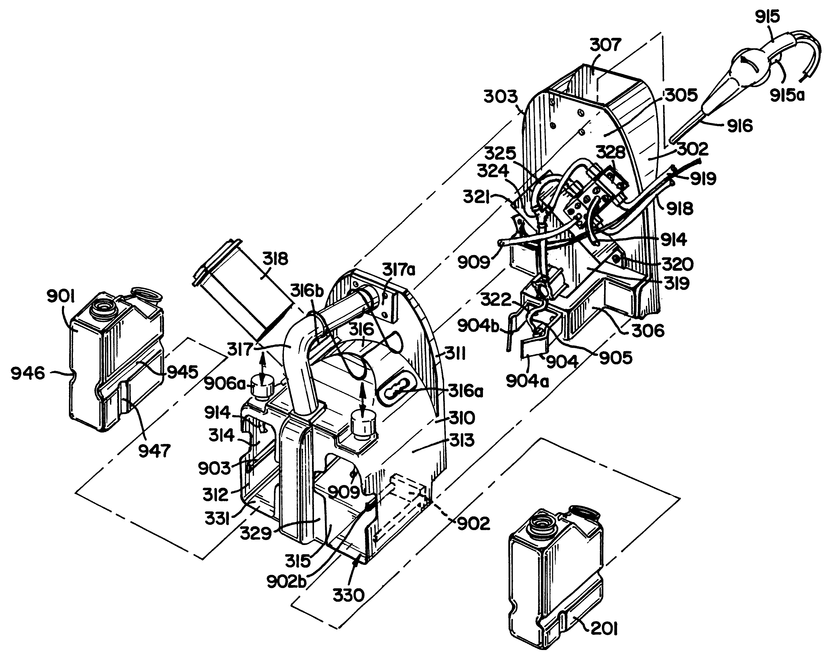
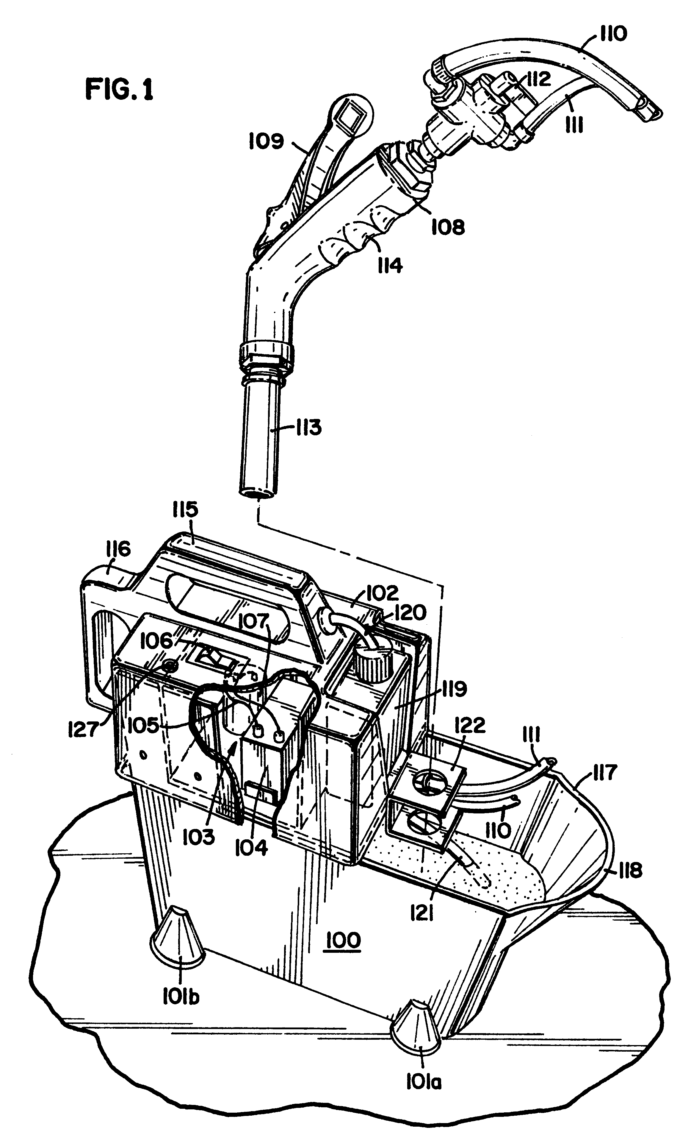
FIG. 1 shows a spray head 113 connected to the pump output of the dilution section. Two sources 110 and 111 are shown for the diluted concentrate and the rinse. The spray is energized by compressing handle 109 which permits either rinse or diluted concentrate to exit the spray head in a spray pattern. The rinse or the diluted concentrate is selected using valve 112. The spray head is typically constructed from conventional metallic and thermoplastic materials. The spray head can be adapted for one, two or more diluted concentrate streams and a rinse stream. The selection of the rinse or diluted concentrate stream can be made at valve 112 in the spray head or in the dilution section 102 by selecting the appropriate concentrate and venturi. The dilution system of the invention includes a container 100 for an aqueous diluent such as service water. The container is typically a molded unit made from a thermoplastic material. Such a unit can be injection molded, vacuum molded or shaped us...


PUM

PropertyMeasurementUnit
volumeaaaaaaaaaa
volumeaaaaaaaaaa
volumeaaaaaaaaaa

Abstract

The invention includes a first dispenser for providing a first dilute concentrate of a use solution in a bottle. This bottle is then used in a portable delivery/dilution device which provides for a second level of concentration of the use solution. The bottles in which the solution is placed has both a vertical and horizontal lockout. The horizontal lockout is useful in making certain the right bottles are utilized with each dispenser and the vertical lockouts are useful in guiding the bottle upwards as the first concentration of liquid is placed in the bottle. The portable delivery/dilution system is easily portable, easily filled with water which can be easily poured from a system after use. The battery is rechargeable and can be used in most any application where spraying is desired. First and second timers activate first and second indicators to notify the user sufficient use solution has been dispensed.

Description

The invention relates to a fully integrated dilution station using a unique combination of mechanical, electrical and liquid elements in a station that combines a diluent with a liquid concentrate to form a composition that is sprayed or formed onto a surface. The dilution station can also pump and spray the aqueous diluent as a spray rinse. The dilution station has a container for the aqueous diluent that is designed and configured to be fillable from a tub spout and to be easily emptied without disassembly when cleaning is finished. The integrated unit has one, two or more sources of liquid concentrate and an associated venturi for diluting and spraying each concentrate. The integrated system is powered by a portable power source such as an electric pump and a rechargeable battery having sufficient electrical capacity to enable a custodial or maintenance personnel to complete a substantial number of cleaning tasks between recharging or replacing the batteries. The invention also r...

Claims


Application Information

Patent Timeline
Patent Type & Authority Patents(United States)
IPC IPC(8): B08B3/02B67D5/32B67D5/33B67D5/56C11D17/04C11D1/66B67D7/34B67D7/74
CPCB05B7/2443B05B7/2472B08B3/026C11D17/046B67D7/74C11D1/66C11D17/041B67D7/344
Inventor TOETSCHINGER, MARK J.DAWSON, MARY M.PEDERSEN, DANIEL E.
Owner ECOLAB USA INC
Why Eureka
Try Eureka