Operand supply to an execution unit

Inactive Publication Date: 2001-09-11
ARM LTD
View PDF5 Cites 20 Cited by
  • Summary
  • Abstract
  • Description
  • Claims
  • Application Information

AI Technical Summary

Problems solved by technology

This causes a problem in ensuring

Method used


Image

  • Operand supply to an execution unit
  • Operand supply to an execution unit
  • Operand supply to an execution unit

Examples


Embodiment Construction

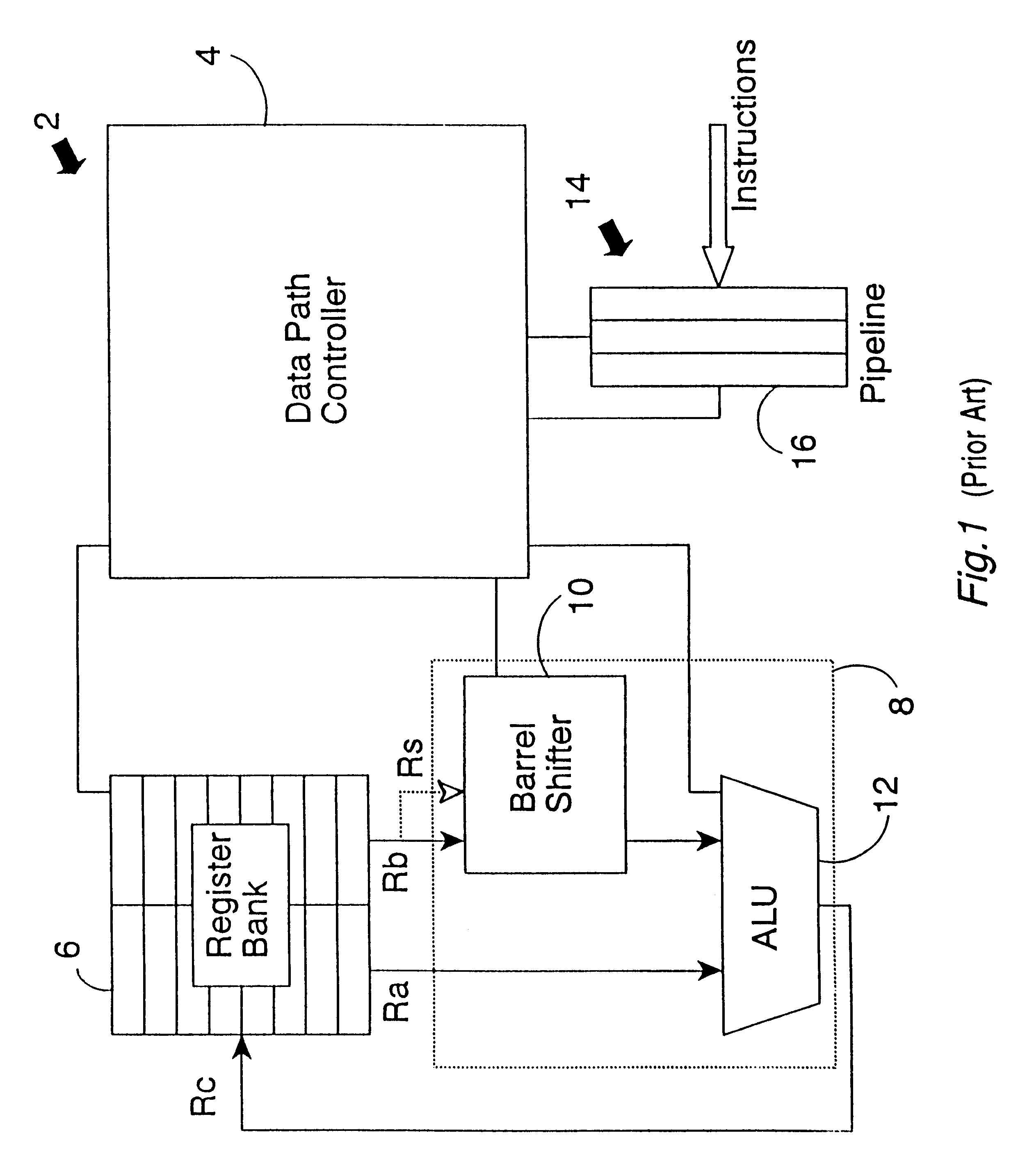
FIG. 1 shows a microprocessor 2 having a data path controller 4, a register bank 6 and an execution unit 8. In this example, the execution unit 8 is illustrated in simplified form as containing only a barrel shifter 10 and an ALU 12. In practice, many more (or different) functional units may be provided within the execution unit 8. An instruction pipeline 14 receives program instruction words from a memory and passes these along the pipeline 14 until they reach an execution stage 16. Fields within the instructions are read by the data path controller 4 prior to the instruction reaching the execution stage in order that the data path controller 4 can set up the register bank 6 and the execution unit 8 appropriately to perform the data manipulation specified by the program instruction.

In the example of FIG. 1, two data values Ra and Rb are to be read from the two read ports of the register bank 6. The data value Rb is to be subjected to a shifting operation by the barrel shifter 10 by...


PUM


Abstract

A microprocessor system comprising a register bank 6 and an execution unit 8 incorporating a barrel shifter 10 and an ALU 12 is provided. The register bank 6 has X read ports whilst at least some of the program instructions require Y input operands to be read from the register bank 6, where Y is greater than X. A cache register 18 is provided that caches previously read input operands for supply to the barrel shifter 10 and if it is detected that the same register is being read a second or subsequent time then this cached value is supplied to the barrel shifter 10 rather than requiring a further read from the register bank 6. A tag register 20 associated with each cache register 18 draws data indicating from which register within the register bank 6 the cached data value was copied. A valid flag 22 indicates that that cached data value is still current, i.e. at the corresponding register within the register bank 6 has not been overwritten.

Description

1. Field of the InventionThis invention relates to the field of data processing. More particularly, this invention relates to data processing systems that include a register bank having a plurality of registers that store operand values to be used by an execution unit in performing a data manipulation under program instruction control.2. Description of the Prior ArtIt is known to provide data processing systems having a register bank made up of a plurality of registers each storing data values to be manipulated or to control manipulation. The operand values within these registers are supplied to an execution unit via read ports of the register bank with the result being written back via one or more write ports to the register bank. Considerations of circuit layout and area vs cost and / or speed mean that it is desirable to provide a limited number of read ports from the register bank that can provide simultaneous read access to different registers within the register bank. Certain pr...

Claims


Application Information

Patent Timeline
IPC IPC(8): G06F9/38G06F9/30
CPCG06F9/383G06F9/30138
Inventor LARRI, GUY
Owner ARM LTD
Why Eureka
Try Eureka