NxN non-blocking optical switch

Inactive Publication Date: 2001-09-18
JDS UNIPHASE INC
View PDF3 Cites 40 Cited by
  • Summary
  • Abstract
  • Description
  • Claims
  • Application Information

AI Technical Summary

Benefits of technology

In many instances, monitoring of a beam of light emerging from the optical switch is required. A small fraction, or tap, of optical power distributed to a specified port is used to monitor and ensure a specified intensity or integrity, i.e., switch state.
Under some circumstances a GMZI may drift- the specified intensity or integrity may change under a specific operational condition. The integrity of a beam of light may be compromised by contamination from other

Problems solved by technology

A new path is provided from any input port to any output port; however, to pr

Method used


Image

  • NxN non-blocking optical switch
  • NxN non-blocking optical switch
  • NxN non-blocking optical switch

Examples


Example

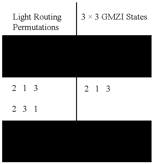
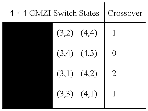
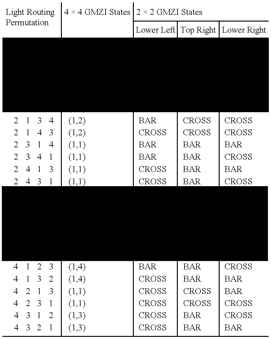
Expanded Capacity Switching and N.times.N Non-blocking Switching

Referring to FIG. 1, the basic layout of an N.times.N GMZI 5 consists of three components: an N.times.N MMI splitter 20; an active phase shifting region 22 having N optical path length changers in the form of phase shifters 28 in the active phase shifting region 22; and an N.times.N MMI combiner 24. The MMI splitter 20 is illustrated as a substantially rectangular body; one side of the rectangular body having input ports 4 and the opposing side of the rectangular body having output waveguides. The MMI combiner 24 is illustrated as a substantially rectangular body, one side of the rectangular body having output ports 6 and the opposing side having input waveguides. In the N.times.N GMZI 5, the output waveguides of the N.times.N MMI splitter 20 and the input waveguides of the N.times.N MMI combiner 24 are coupled and form waveguide arms 26 between the N.times.N MMI splitter 20 and the N.times.N MMI combiner 24. Commonly, ...


PUM


Abstract

Combinations of optically coupled Generalized Mach-Zehnder Interferometers (GMZIs) result in switches of greater switching capacity than an isolated GMZI. In a preferred form, the present invention provides a balanced non-blocking switch by using symmetrical configurations of optically coupled GMZIs, and also provides a cascaded non-blocking switch by cascading an NxN GMZI with a (N-1)x(N-1) non-blocking switch.

Description

This invention relates generally to optical communication systems and the like. In particular, the present invention relates to optical switches having a greater number of switching states than a conventional Generalized Mach-Zehnder interferometer (GMZI). One embodiment of this invention relates to an N.times.N non-blocking optical switch.As we move towards the realization of widespread fiber optic networks, it is becoming increasingly important to provide optical switching at the optical network nodes. Optical switching is expected to become increasingly important as wavelength division multiplexing expands the number of optical paths available. By using integrated optical components to perform network node routing functions, advantages in terms of functionality, size, speed, and efficiency are achievable.The integrated optical multimode interference (MMI) coupler has been the subject of much attention and research in recent years, see for example: L. B. Soldano, et al. in a paper...

Claims


Application Information

Patent Timeline
IPC IPC(8): G02F1/313G02F1/29H04Q11/00G02F1/01G02F1/21G02B6/12G02B6/28G02F1/225G02B6/34
CPCG02B6/12011G02B6/12033H04Q11/0001H04Q11/0005G02F1/3136G02B6/2813G02B2006/12145G02F1/225H04Q2011/0035G02F2001/212G02F2001/217G02F1/217G02F1/212
Inventor LAGALI, NEIL S.MACDONALD, IANPAIAM, REZA
Owner JDS UNIPHASE INC
Why Eureka
Try Eureka