Ballast for a discharge lamp

a discharge lamp and ballast technology, applied in the field of ballast for a discharge lamp, can solve the problems of unnecessary high voltage, possible electrical shock hazards for personnel, undue stress on the components of the starter

Inactive Publication Date: 2001-09-25
MATSUSHITA ELECTRIC WORKS LTD
View PDF2 Cites 45 Cited by
  • Summary
  • Abstract
  • Description
  • Claims
  • Application Information

AI Technical Summary

Problems solved by technology

A problem remains in the ballast that, even if the ballast is deactivated as a consequence of that the discharge lamp fails to start due to absence of the lamp or the lamp reaching its end of operation life, the residual capacitance in the capacitor of the booster may cause the starter to develop the st

Method used


Image

  • Ballast for a discharge lamp
  • Ballast for a discharge lamp
  • Ballast for a discharge lamp

Examples


first embodiment

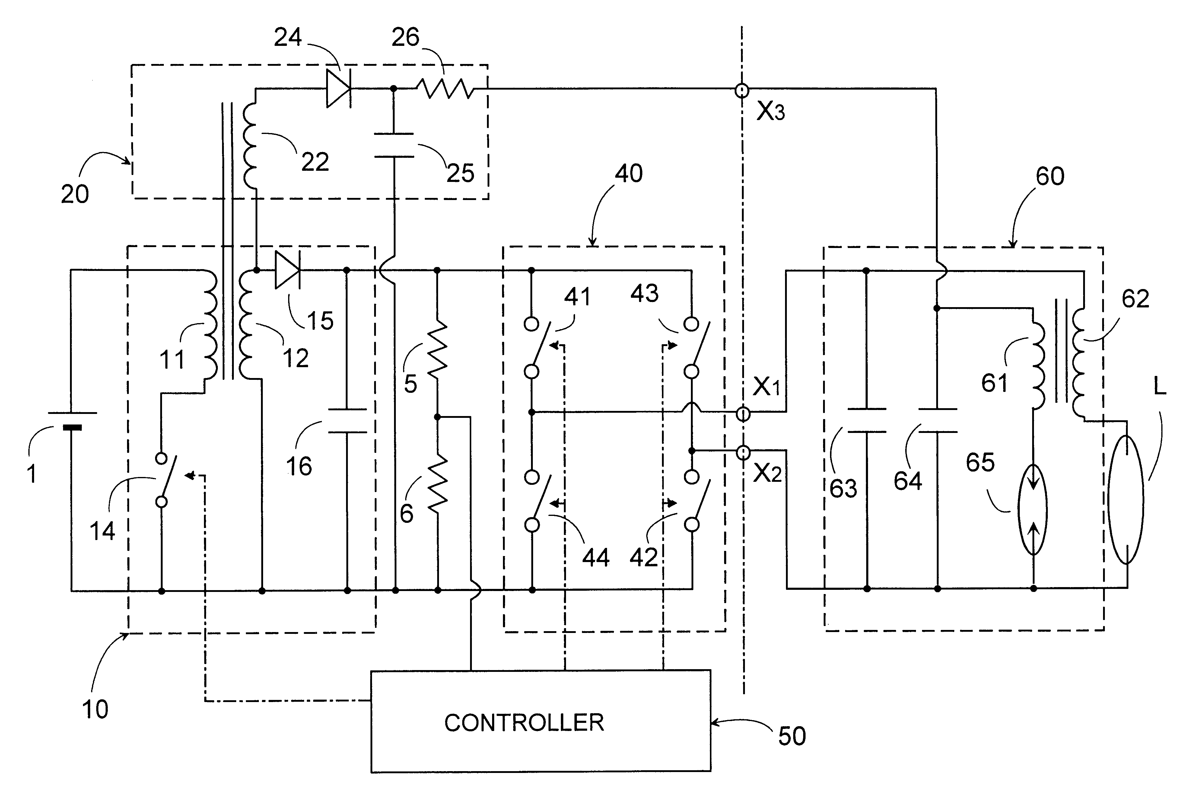
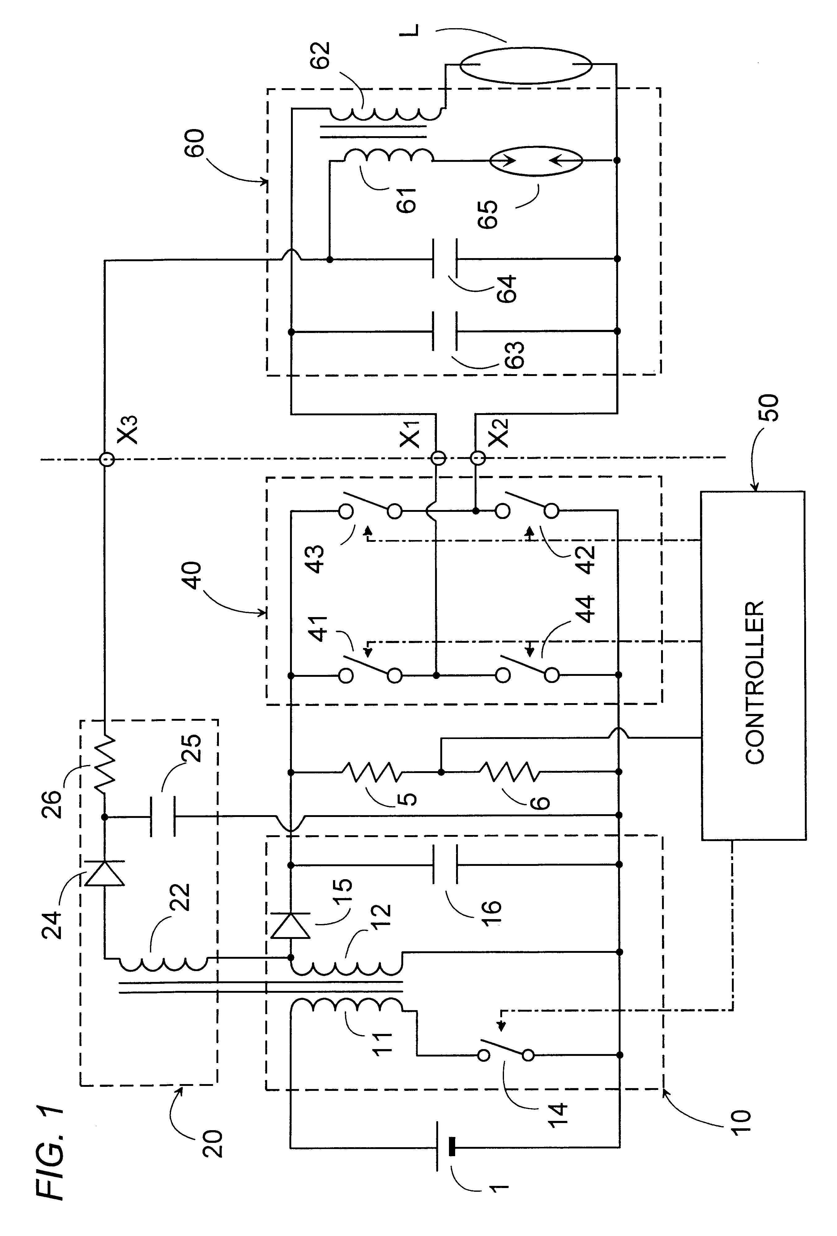
Referring now to FIG. 1, there is shown a ballast for a discharge lamp in accordance with a first embodiment of the present invention. The ballast is suitable for operating a high intensity discharge lamp for use as a headlamp of an automobile and a light source of LCD projector. The ballast comprises a DC-to-DC converter 10 adapted to be connected to a DC power source 1, such as a car battery or the like fixed voltage source, for providing a DC power, a booster 20 connected to the DC voltage source 1 through the converter 10 to generate a boosted voltage, and an inverter 40 receiving the DC power from the converter 10 and proving an AC power for operating the discharge lamp L. The booster 20 is connected to provide the boosted DC voltage to a starter 60 which responds to generate a starting voltage of sufficiently high level for starting the lamp L. Also included in the ballast is a power controller 50 which is responsible for controlling the converter 10 and the inverter 40 to sta...

second embodiment

FIG. 8 shows a ballast in accordance with a second embodiment of the present invention which is identical to the first embodiment except that a booster 20D is integrated in the inverter 40D. Like parts are designated by like numerals with a suffix letter of "D". The booster 20D includes a series combination of a diode 37, a resistor 31D, and a capacitor 32D connected across transistor 44D, and a transformer with a primary winding 33D and a secondary winding 34D. The primary winding 33D is connected in series with a bi-directional thyristor 35D across capacitor 32D, while the secondary winding 34D is connected in series with a diode 36D across the capacitor 25D. While the transistor 41D is on, capacitor 32D is charged through diode 37 and resistor 31D by the DC voltage from capacitor 16D of the converter 10D. As the capacitor 32D is charged up to a break-over voltage of thyristor 33D, thyristor 33D becomes conductive to initiate an oscillation in a closed circuit of capacitor 32D, th...

third embodiment

FIG. 10 shows a ballast in accordance with a third embodiment which is identical to the second embodiment except that a booster 20F is connected differently with the inverter 40F. Like parts are designated by like numerals with a suffix letter of "F". The booster 20F comprises a series combination of a diode 37F, a resistor 31F, and a capacitor 32F connected across a transistors 43F, and a transformer with a primary winding 33F and a secondary winding 34F. The primary winding 33F is connected in series with a bi-directional thyristor 35F across capacitor 32F, while the secondary winding 34F is connected in series with a diode 36F across the capacitor 25F. While the transistor 42F are on, capacitor 32F is charged through diode 37F and resistor 31F by the DC voltage from capacitor 16F of the converter 10F. As capacitor 32F is charged up to a break-over voltage of thyristor 33F, thyristor 33F becomes conductive to initiate an oscillation in a closed circuit of capacitor 32F, thyristor ...


PUM


Abstract

A safety ballast for a discharge lamp capable of interrupting the supply of the electric power upon failure of starting the lamp. The ballast includes a converter providing a DC power voltage from a DC voltage source, a booster providing a boosted DC voltage to a starter which generates, based upon the boosted DC voltage, a starting voltage for starting the lamp, and an inverter receiving the DC power from the converter to provide an AC power for operating the lamp. The booster includes a capacitor which is charged by the DC power and accumulate the boosted voltage. A controller monitors a load condition of the lamp and issues a disable signal when a no-load condition continues over a predetermined starting period. The inverter includes a plurality of switching elements one of which is regulated to be turned on in response to the no-load signal for establishing a supply path of supplying the boosted voltage from the booster's capacitor through the switching element to the starter. The one switching element is also controlled to be turned off in response to the disable signal for interrupting the supply path. Thus, when the no-load condition continues over the predetermined starting period as indicative of the that the lamp has been removed or the lamp reaching its end of life, the booster's capacitor bearing the boosted voltage is disconnected from the starter, applying no voltage to the starter and therefore preventing the starter from being activated to generate unnecessary starting voltage.

Description

1. Field of the InventionThe present invention is directed to a ballast for a discharge lamp, more particularly a high density discharge lamp such as a metal halide lamp and a mercury lamp.2. Description of the Prior ArtAs disclosed in Japanese Laid-Open Patent Publication No. 7-142182, a prior ballast for a discharge lamp is generally known to have a DC-to-DC converter supplying a DC voltage from a DC voltage source, a DC-to-AC inverter providing an AC voltage from the DC voltage source for operating the discharge lamp, a booster generating a boosted DC voltage, and a starter receiving the boosted voltage and providing a starting voltage of sufficiently high level for starting the lamp. The booster includes a capacitor which accumulates the boosted DC voltage to be supplied to the starter for developing the starting voltage. A problem remains in the ballast that, even if the ballast is deactivated as a consequence of that the discharge lamp fails to start due to absence of the lamp...

Claims


Application Information

Patent Timeline
IPC IPC(8): H02M3/24H02M3/335H02M7/48H05B41/28H05B41/292
CPCH02M3/33507H02M7/4807H05B41/2925H02J2009/007Y10S315/05Y02B20/208H02M2001/007H02J9/007H02M1/007Y02B20/00
Inventor NAGASE, HARUOSATOU, NORIYUKITAGA, YOSHITAKAKATAOKA, HISAOUENO, MASATOSHI
Owner MATSUSHITA ELECTRIC WORKS LTD
Why Eureka
Try Eureka