System and method for distance measurement by inphase and quadrature signals in a radio system

a radio system and signal technology, applied in the field of distance measurement, can solve the problems of inability to meet the requirements of commercial applications, delay required, and high complexity of the system of determining the position of objects,

Inactive Publication Date: 2001-09-25
HUMATICS CORP
View PDF45 Cites 160 Cited by
  • Summary
  • Abstract
  • Description
  • Claims
  • Application Information

AI Technical Summary

Problems solved by technology

The global positioning satellite (GPS) system operated by the United States Department of Defense, for example, is a highly complex system of determining the position of an object by distance measurement.
The system usually requires two passes of the satellite, necessitating a wait of more than 100 minutes.
Although the TRANSIT satellite system is capable of high accuracy (on the order of one meter), the delay required is unacceptable for commercial applications.
Although these systems accurately measure the distance between objects. they are extremely complex, and, more importantly, expensive to implement.
Also, response times of (GPS and TRANSIT satellite systems are typically slow due to their narrow bandwidth.

Method used


Image

  • System and method for distance measurement by inphase and quadrature signals in a radio system
  • System and method for distance measurement by inphase and quadrature signals in a radio system
  • System and method for distance measurement by inphase and quadrature signals in a radio system

Examples


Embodiment Construction

Overview of the Invention

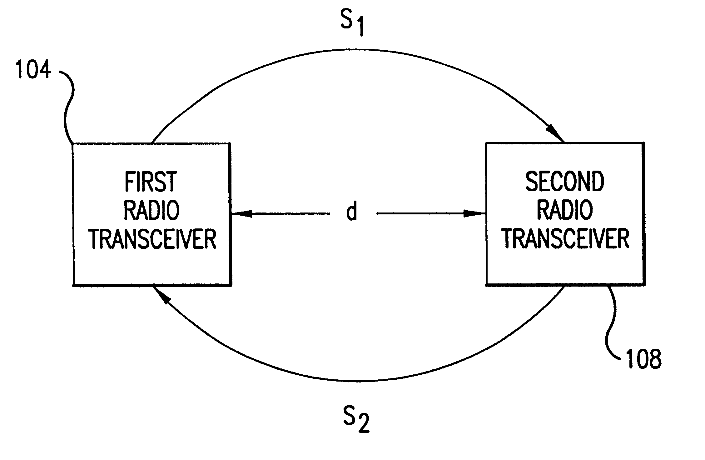
The present invention is directed to a system and a method for distance measurement using a radio system. The present invention can be used to measure the distance between a plurality objects.

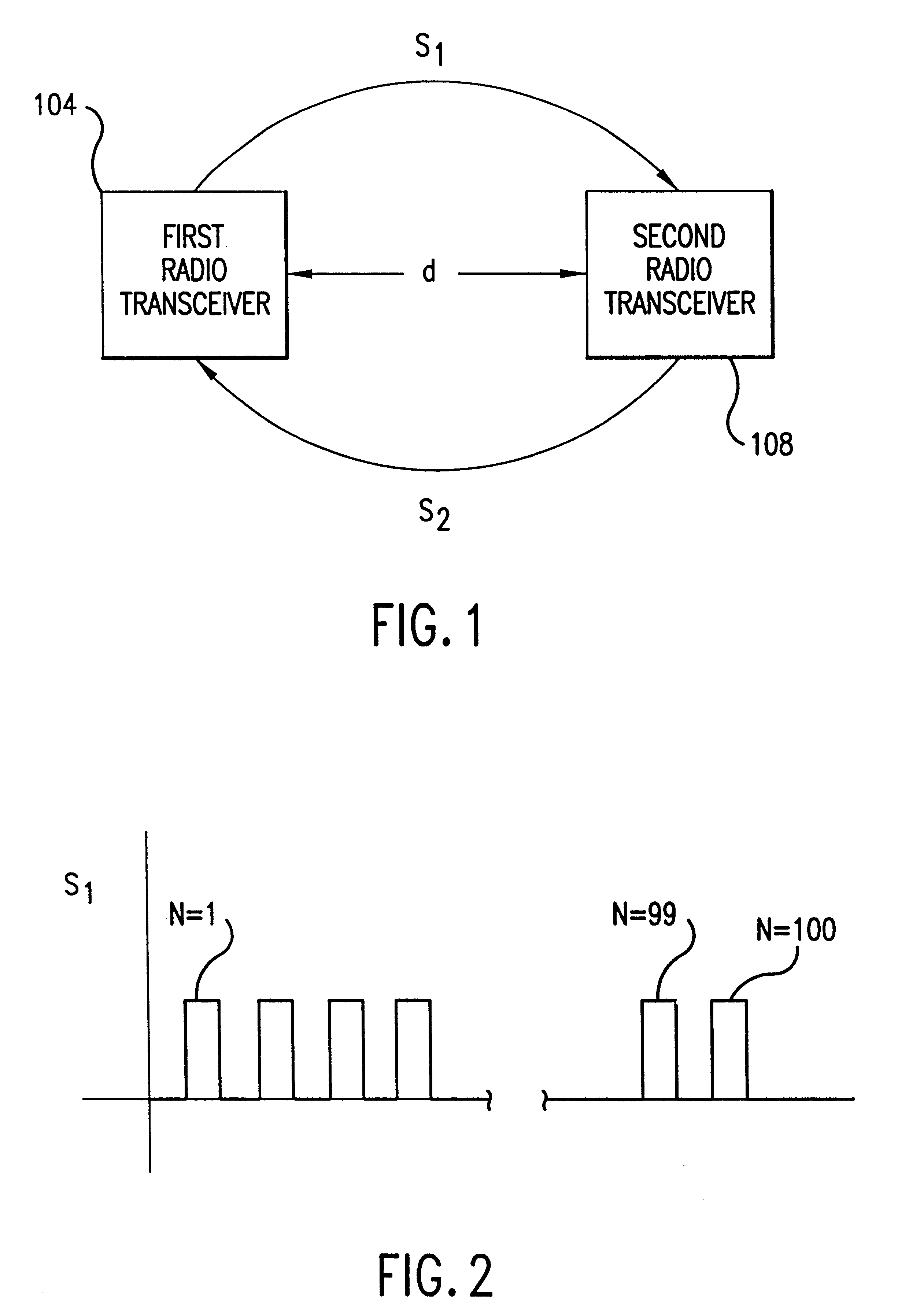
Briefly stated, the key to measuring a distance according to the present invention is to precisely measure the time it takes for a single bit to travel from a first radio transceiver to a second radio transceiver. Since in reality it is difficult to transmit and receive a single bit, the distance is measured by determining the time it takes a pulse train to travel from a first radio transceiver to a second radio transceiver and then from the second radio transceiver back to the first radio transceiver. Stated in other terms, the distance is measured by determining the travel time for a complete exchange of data between the first and second radio transceivers.

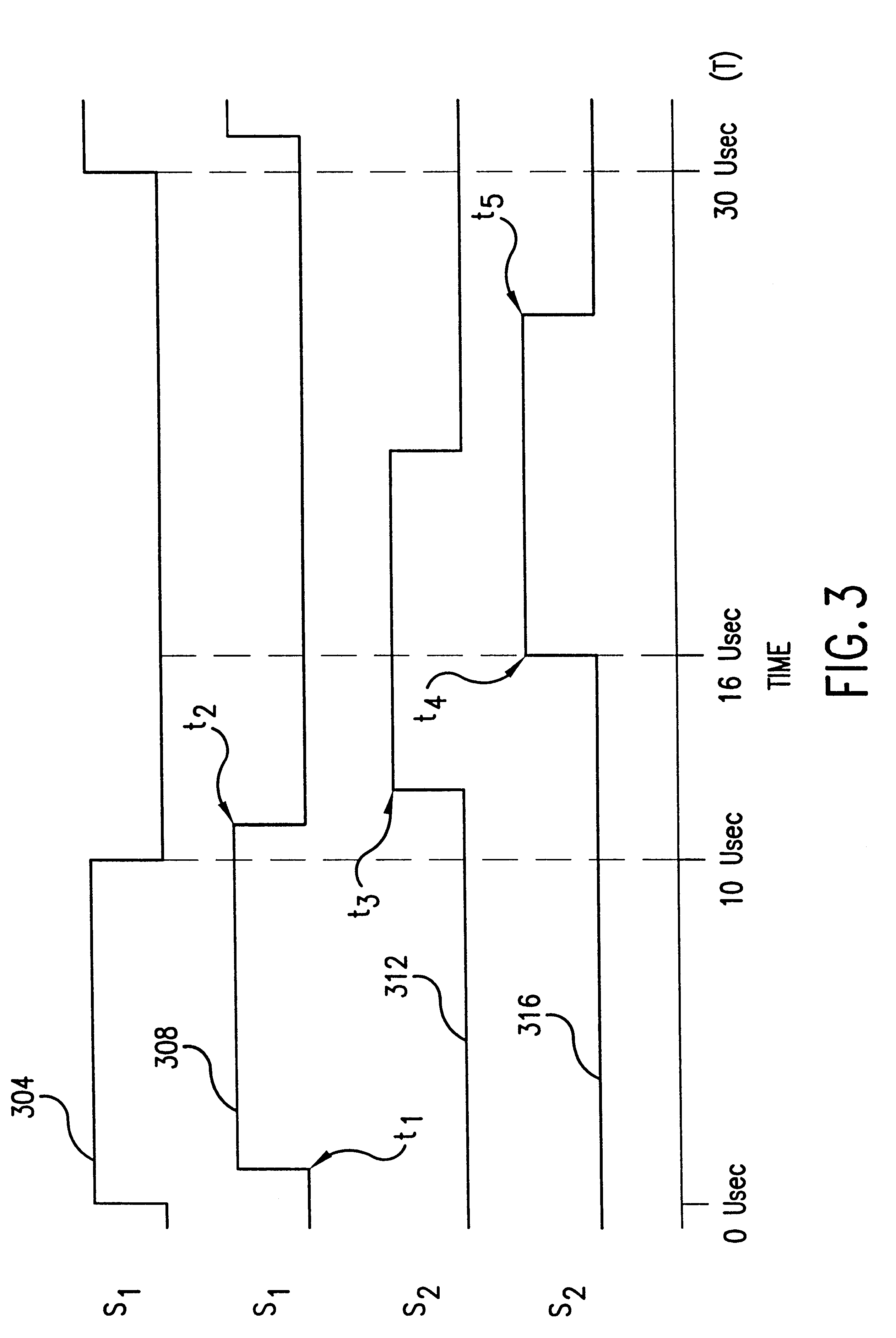
The actual distance measurement is a two step process. In the first step the distance is measured in coarse resol...


PUM


Abstract

A system and a method for distance measurement utilizes a radio system. The distance is measured by determining the time it takes a pulse train to travel from a first radio transceiver to a second radio transceiver and then from the second radio transceiver back to the first radio transceiver. The actual measurement is a two step process. In the first step, the distance is measured in coarse resolution, and in the second step, the distance is measured in fine resolution. A first pulse train is transmitted using a transmit time base from the first radio transceiver. The first pulse train is received at a second radio transceiver. The second radio transceiver synchronizes its time base with the first pulse train before transmitting a second pulse train back to the first radio transceiver, which then synchronizes a receive time base with the second pulse train. The time delay between the transmit time base and the receive time base can then be determined. The time delay indicates the total time of flight of the first and second pulse trains. The time delay comprises coarse and fine distance attributes. The coarse distance between the first and second radio transceivers is determined. The coarse distance represents the distance between the first and second radio transceivers in coarse resolution. An in phase (I) signal and a quadrature (Q) signal are produced from the time delay to determine the fine distance attribute. The fine distance indicates the distance between the first and second transceivers in fine resolution. The distance between the first and second radio transceivers is then determined from the coarse distance and the fine distance attributes.

Description

1. Field of the InventionThe present invention generally relates to distance measurement and more specifically to a system and method for distance measurement by in phase and quadrature signals in a radio system.2. Related ArtDistance measurement systems are required in a wide variety of applications. Sunveying, position determination, precision farming and mining are some example applications that require distance measurement systems.In recent years, various systems for distance measurement systems have been developed. The global positioning satellite (GPS) system operated by the United States Department of Defense, for example, is a highly complex system of determining the position of an object by distance measurement. The GPS system depends on measuring the time-of-flight of signals from three or more orbiting satellite transmitters by a navigation receiver. According to the GPS system, each satellite broadcasts a time-stamped signal that includes the satellite's emphasis. i.e., ...

Claims


Application Information

Patent Timeline
Patent Type & Authority Patents(United States)
IPC IPC(8): G01S13/00G01S13/76G01S13/08G01S13/86
CPCG01S13/08G01S13/76G01S13/87G01S13/913G01S13/765
Inventor RICHARDS, JAMES L.FULLERTON, LARRY W.MEIGS, DAVID C.STANLEY, RANDALL S.COWIE, IVAN A.
Owner HUMATICS CORP
Why Eureka
Try Eureka