
Failure detection system

a failure detection and detection system technology, applied in error detection/correction, digital computer details, instruments, etc., can solve the problems of gps alone being unsatisfactory as a sole means of navigation for civil aviation users, slow increase in range bias error, and inability to monitor the integrity of the gps integrity monitoring system in the operation control system,

Inactive Publication Date: 2001-10-02
NORTHROP GRUMMAN SYST CORP +1
View PDF5 Cites 34 Cited by
  • Summary
  • Abstract
  • Description
  • Claims
  • Application Information

AI Technical Summary

Benefits of technology

The invention is a method and apparatus for determining a failure in a subsystem that is part of a system, the system being characterized in terms of a state vector comprising a plurality of state variables. The state vector is updated at times (jK+k)T.DELTA.t using one or more Kalman filter processes, j taking on integer values, K being a predetermined integer, k taking on integer values between 1 and K for each value of j, T being a predetermined integer, and .DELTA.t being a predetermined time interval. The method comprises the steps: (a) executing at present time a plurality of Kalman filter processes where one of the Kalman filter processes determines the state vector at present time minus (K-1)T.DELTA.t using data from subsystems without failures; (b) determining the values of one or more statistical measures of one or more residuals for each of one or more Kalman filter processes for one or more time periods equal to or greater than T.DELTA.t; and (c) determining a subsystem failure from the one or more values of the statistical measures.

Problems solved by technology

GPS by itself is unsatisfactory as a sole means of navigation for civil aviation users.
However, a slowly increasing range bias error could occur due to satellite clock faults or due to errors in the uploaded data introduced as a result of human errors at the GPS Operational Control System Facility.
The present GPS integrity-monitoring system in the Operation Control System may take hours.
However, the availability of the six satellites required for sole means is only 60 or 70 percent, which is totally inadequate.
It would therefore not be capable of meeting the accuracy requirement during such integrity outage periods.
Since such periods can last more than an hour, the accuracy requirement cannot be achieved with an IRS uncalibrated by GPS.
The problem with calibrating the IRS with GPS using a conventional Kalman filter is that a GPS failure can contaminate the integrated GPS / IRS solution before the failure is detected.
If the GPS failure causes a pseudorange error drift of less than one meter / sec., it cannot be detected by tests of the Kalman filter residuals.

Method used


Image

  • Failure detection system
  • Failure detection system
  • Failure detection system

Examples


Embodiment Construction

The purpose of the failure detection system is to identify the satellites whose clock drifts are within specification and to use only those satellites within specification in estimating the user's position.

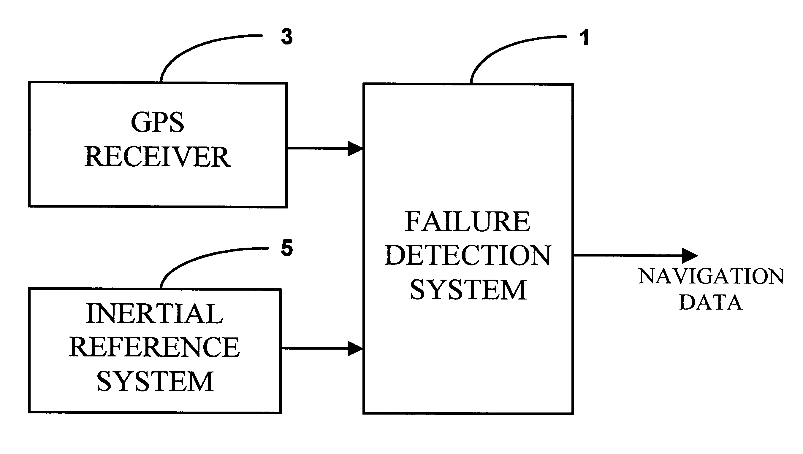
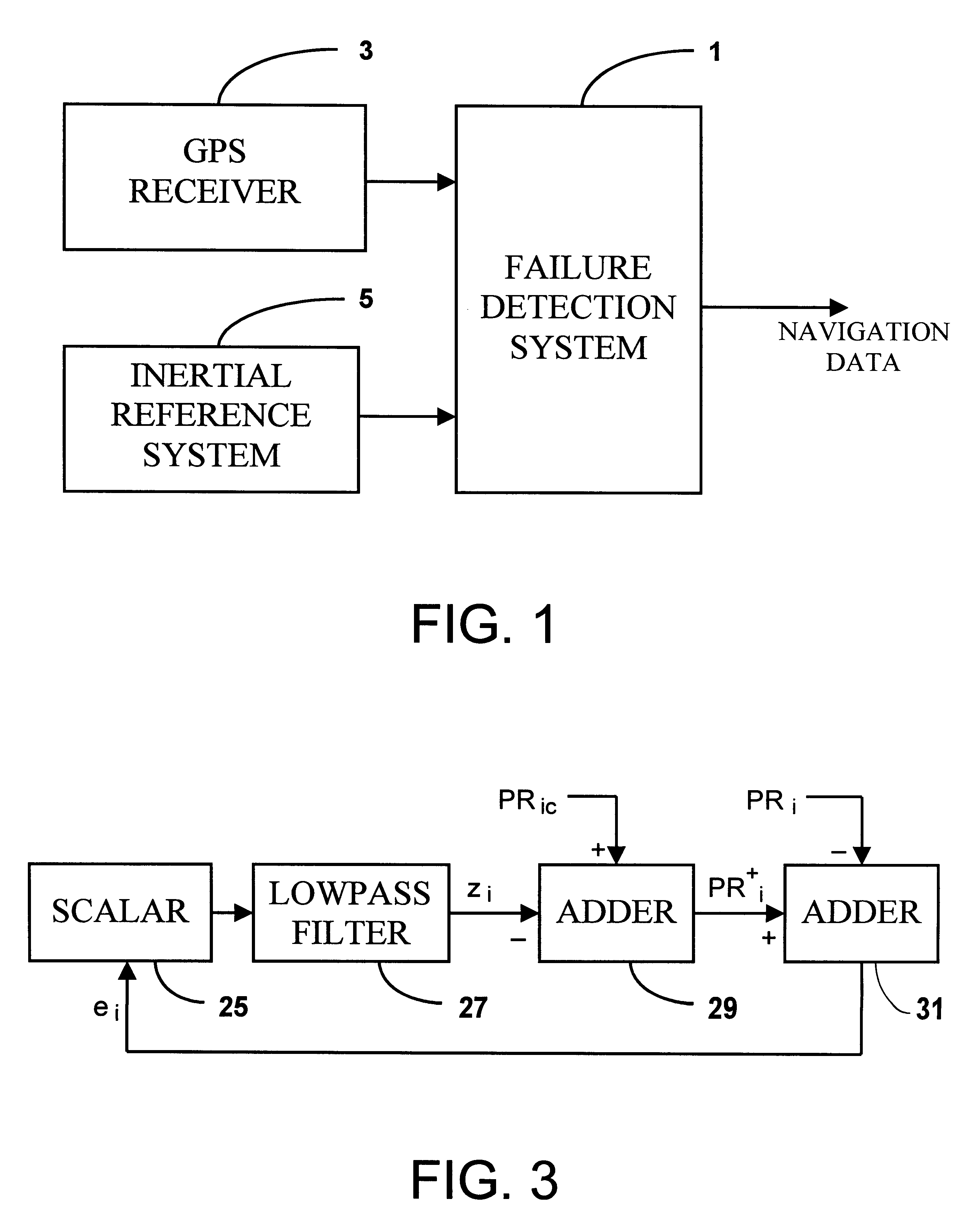
As shown in FIG. 1, the failure detection system 1 operates in conjunction with a GPS receiver 3 and an inertial reference system 5 to produce navigation data for the platform on which it is installed by means of a Kalman filter process. The preferred embodiment of the failure detection system utilizes an Intel 80960 microprocessor and memory resources.

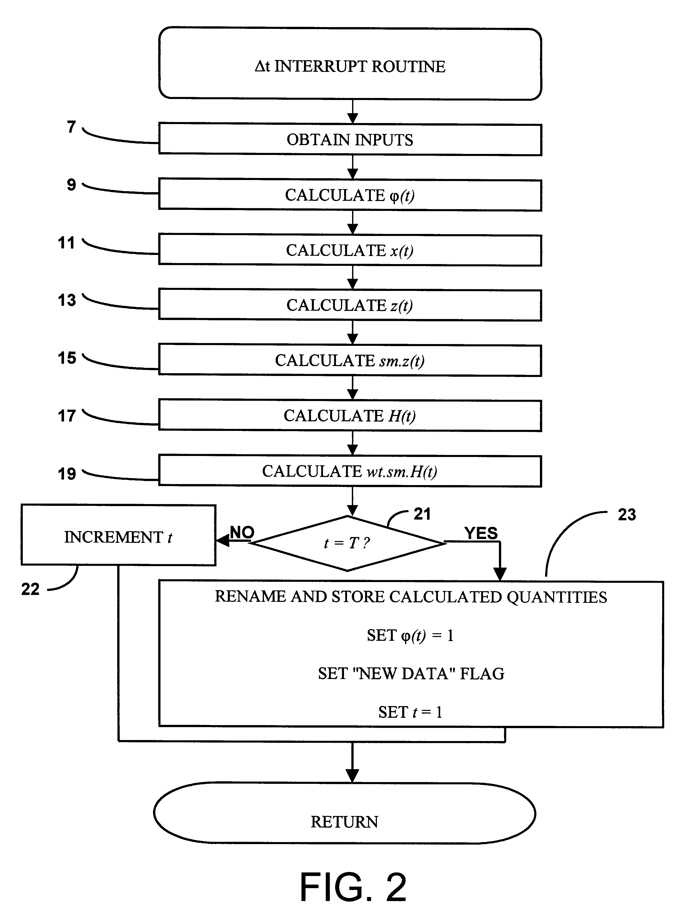
The interrupt routine shown in FIG. 2 details the operations regularly performed by the failure detection system at .DELTA.t intervals where at for the preferred embodiment is 1 second. In step 7, input data is obtained from the GPS receiver 3 and the inertial reference system 5.

The GPS receiver 3 supplies ARINC 743 quantities comprising the pseudorange PR.sub.i to each satellite i within view and the coordinates X.sub.Si, Y.sub.Si,...


PUM


Abstract

The invention is a method and apparatus for determining a failure in a subsystem that is part of a system, the system being characterized in terms of a state vector comprising a plurality of state variables. The state vector is updated at times (jK+k)TDELTAt using one or more Kalman filter processes, j taking on integer values, K being a predetermined integer, k taking on integer values between 1 and K for each value of j, T being a predetermined integer, and DELTAt being a predetermined time interval. The method comprises the steps: (a) executing at present time a plurality of Kalman filter processes where one of the Kalman filter processes determines the state vector at present time minus (K-1)TDELTAt using data from subsystems without failures; (b) determining the values of one or more statistical measures of one or more residuals for each of one or more Kalman filter processes for one or more time periods equal to or greater than TDELTAt; and (c) determining a subsystem failure from the one or more values of the statistical measures.

Description

STATEMENT REGARDING FEDERALLY SPONSORED RESEARCH AND DEVELOPMENT(Not Applicable)This invention relates generally to navigation systems and apparatus and more particularly to integrated radio-inertial navigation systems and apparatus.The National Aeronautical Association has described the Global Positioning System as "the most significant development for safe and efficient navigation and surveillance of air and spacecraft since the introduction of radio navigation 50 years ago." The Global Positioning System (GPS) consists of 24 globally-dispersed satellites with synchronized atomic clocks that transmit radio signals. Time, as measured by each satellite, is embedded in the transmitted radio signal of each satellite. The difference between the time embedded in a satellite's radio signal and a time measured at the point of reception of the radio signal by a clock synchronized to the satellite clocks is a measure of the range of the satellite from the point of reception. Since the clock...

Claims


Application Information

Patent Timeline
Patent Type & Authority Patents(United States)
IPC IPC(8): G01S1/00G01S5/14G01S19/05G01S19/11G01S19/21G01S19/29G01S19/46
CPCG01S19/23G01S19/47
Inventor DIESEL, JOHN W.
Owner NORTHROP GRUMMAN SYST CORP
Learn More