Self-supporting construction element of expanded plastics, in particular for manufacturing floor elements and walls of buildings in general
Inactive Publication Date: 2001-10-09
PLASTEDIL
View PDF14 Cites 108 Cited by
Summary
Abstract
Description
Claims
Application Information
AI Technical Summary
This helps you quickly interpret patents by identifying the three key elements:
Problems solved by technology
Method used
Benefits of technology
Benefits of technology
Advantageously, the construction element of the invention may achieve at one time both adequate self-supporting features, as conferred thereon by the reinforcing section bar integrated within the mass of expanded plastics, and adequate fire-resisting properties thanks to the presence of the lath, which is securely held by the same reinforcing section bar.
In addition, this surface thermal treatment of the construction element may be preceded by a step of scraping the construction element surface, directed to removing the outermost layer, the so-called "skin", of the expanded plastics and enabling a more effective surfacethermal treatment.
Problems solved by technology
While construction elements of this kind have on the one hand a light weight, a comparative ease of installation and a low cost, on the other hand their application in the art and flexibility of use have been restrained heretofore by their poor fire-resisting properties.
This inadequate resistance to fire is essentially related to the fact that construction elements made of expanded plastics show an insufficient capability to securely hold outer covering layers, such as the plaster layers used for the outer surface finish.
When exposed to fire, in fact, the expanded plastics soon shrinks into a shapeless mass of reduced volume, with the ensuing separation of the outer covering layers and rapid collapse of the whole structure.
In addition, an undesirable separation of the outer covering layers may be caused in some instances by a premature "aging" of the plastics surface to which these coverings adhere, a separation which may be further fostered by exposure to heat sources, dusts, fumes, vapors, or chemical substances coming from a source close to the construction elements.
Method used
Image
Click on the blue label to locate the original text in one second.
Reading with bidirectional positioning of images and text.
Examples
second embodiment
In the invention, shown in FIG. 3, reference 101 indicates a wall element used for instance for erecting bearing and partition walls in a building.
The wall element 101 has in this case two pairs of side lugs, generally denoted by numerals 18-21, extending from the opposite lateral sides 28, 29 of the central body 2.
The wall element 101 includes a plurality of reinforcing section bars 109 transversely extending across the central body 2 of the construction element throughout the whole thickness thereof.
Thus, in this embodiment, both opposite fins 11, 12 of the reinforcing section bars 109, in this case rectilinear side fins, lie substantially flush with and parallel to the opposite faces 6, 7 of the wall element 101.
The latter may then include a pair of laths 116a, 116b, each adapted to support a respective covering layer 117a, 117b, such as plaster, welded to the opposite fins 11, 12 of the reinforcing section bars 109.
third embodiment
According to the invention, shown in FIG. 4, furthermore, the wall element 101 may include a panel 22 of gypsumpaperboard, wood, rigid plastics, or another suitable material for decorative and / or structural purposes, instead of the lath 116a, for example.
This panel 22 is fixed to the fins 11 of the reinforcing section bars 109 on the face 7 of the wall element 101 in a manner known per se, such as by a set of screws or dowels, not shown.
According to the nature of the selected covering element, having or not structural capabilities, the wall elements 101 of the invention may advantageously achieve load-bearing characteristics, that is being able to independently withstand possible static loads applied thereto.
According to the invention, the construction elements described above can be manufactured by means of a method comprising the steps of:
associating a lathe 16 for supporting at least one layer 17 of a suitable covering material to a fin 11 extending from one end of a reinforcing...
PUM
Property
Measurement
Unit
Thickness
aaaaa
aaaaa
Thickness
aaaaa
aaaaa
Angle
aaaaa
aaaaa
Abstract
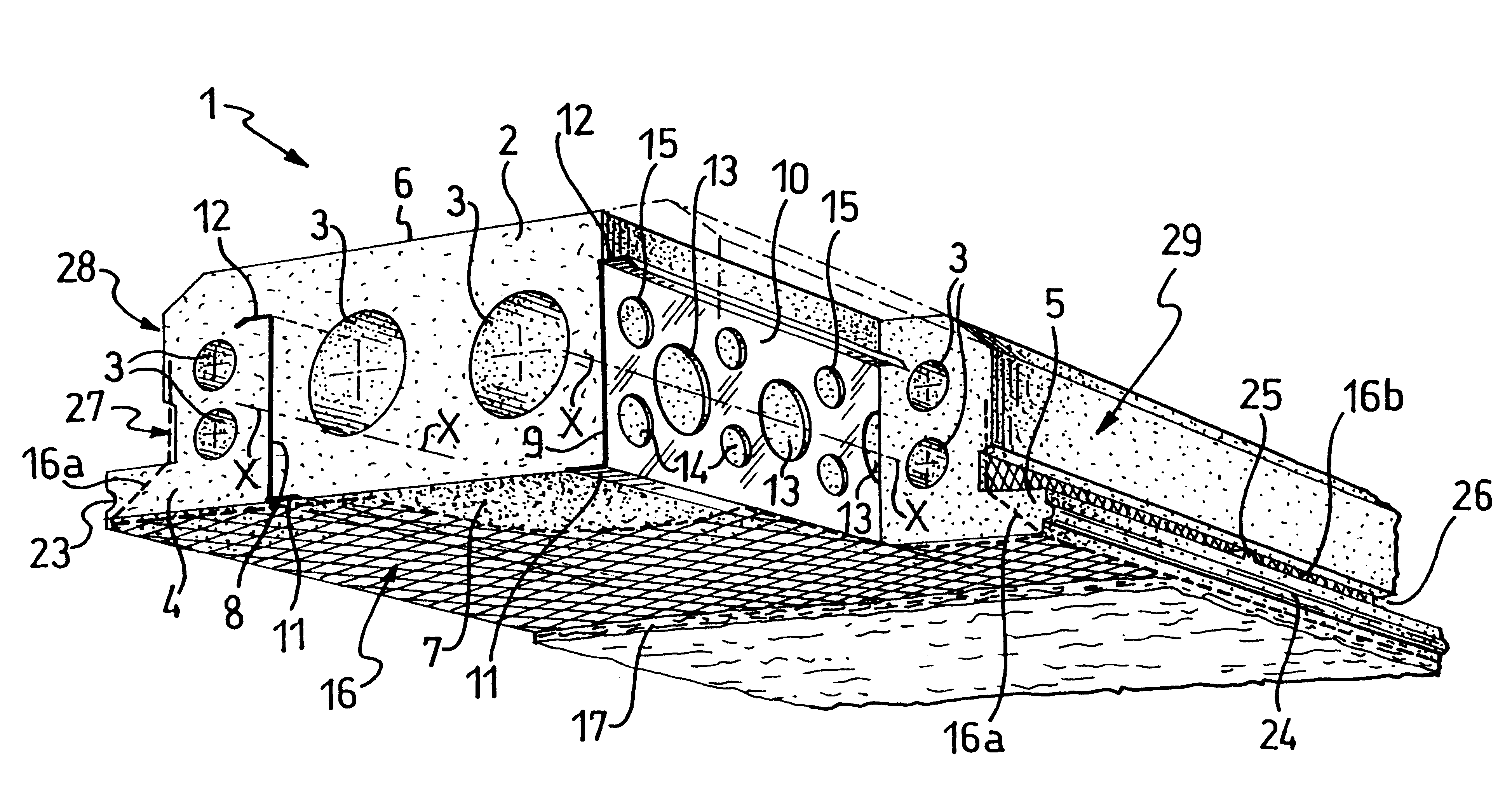
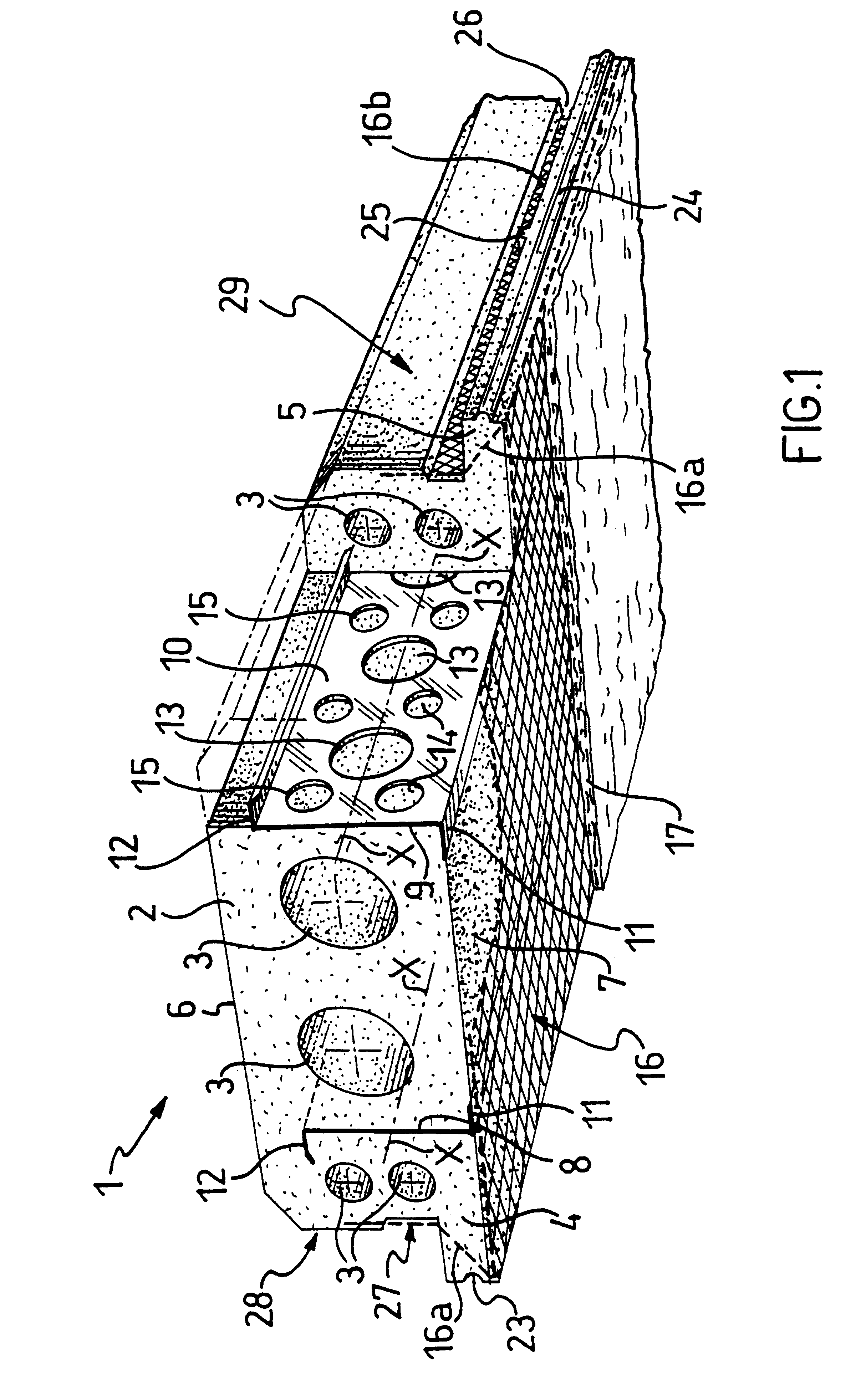
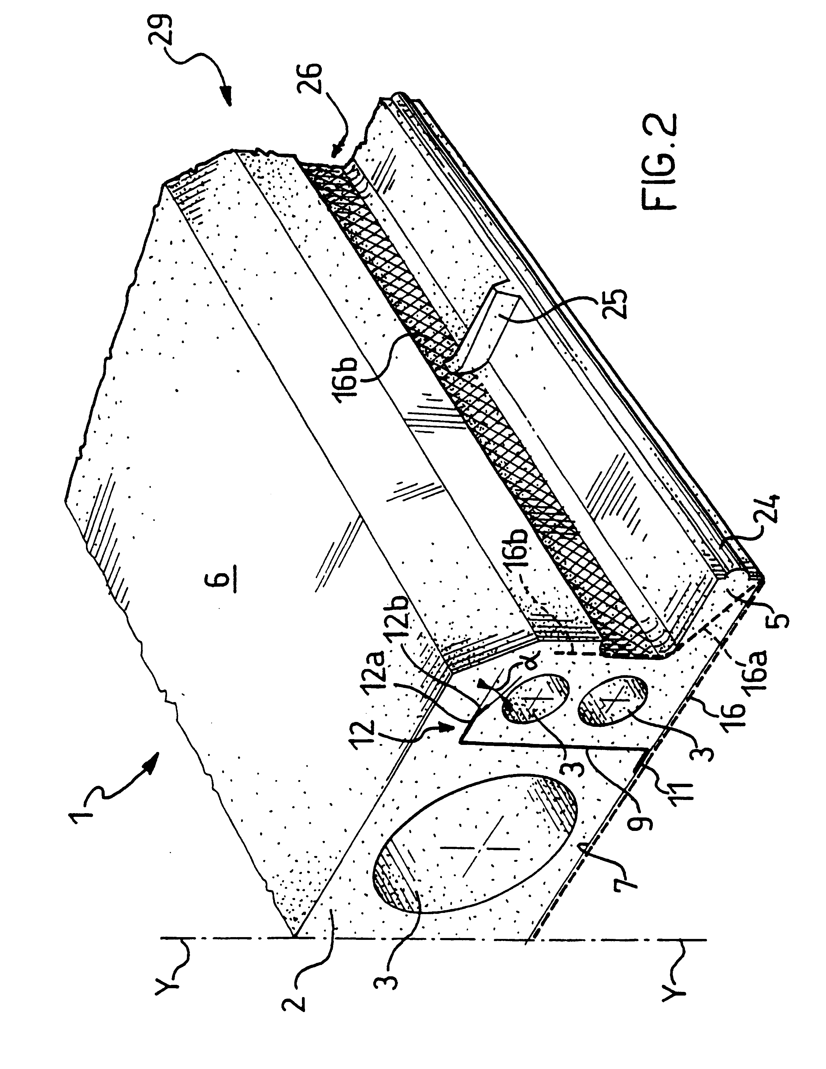
A self-supporting construction element (1, 101) of expanded plastics, in particular for manufacturing floor elements and walls of buildings in general comprises: (1) a central body (2), substantially parallelepipedic in shape and having two opposite faces (6, 7); at least one reinforcing section bar (8,9) transversally extending across the central body (2) between the faces (6,7) thereof and embedded in the expanded plastics; a lath (16) for supporting at least one layer (17) of a suitable covering material, associated to a fin (11,12) of the reinforcing section bar (8,9) lying flush with and substantially parallel to at least one of the faces (6,7) of the construction element (1,101).
Description
This invention relates, in a general aspect thereof, to a self-supporting construction element of expanded plastics material, in particular for manufacturing floor elements and walls of buildings in general.More particularly, the present invention relates to a self-supporting construction element comprising:a) a central body, substantially parallelepipedic in shape, provided with opposite faces;b) at least one reinforcing section bar transversally extending across said central body between said faces and embedded in said expanded plastics.Throughout the description and the appended claims, the terms: self-supporting construction element of expanded plastics, will be used to indicate a section member made of an expanded plastics material, such as expanded polystyrene, which possesses mechanical properties adapted to withstand without structural yielding all the strains applied thereon during its transportation and installation.As is known, the use of construction elements made of exp...
Claims
Application Information
Patent Timeline
Application Date:The date an application was filed.
Publication Date:The date a patent or application was officially published.
First Publication Date:The earliest publication date of a patent with the same application number.
Issue Date:Publication date of the patent grant document.
PCT Entry Date:The Entry date of PCT National Phase.
Estimated Expiry Date:The statutory expiry date of a patent right according to the Patent Law, and it is the longest term of protection that the patent right can achieve without the termination of the patent right due to other reasons(Term extension factor has been taken into account ).
Invalid Date:Actual expiry date is based on effective date or publication date of legal transaction data of invalid patent.

