Brake pad wear sensor

a technology of wear sensor and brake pad, which is applied in the direction of braking system, force/torque/work measurement apparatus, instruments, etc., can solve the problems of failure of indicators that locate electrical circuitry or sensitive components, the amount of wear left on the brake pad, and the design of the brake pad life being cut shor

Inactive Publication Date: 2001-10-16
YAZAKI NORTH AMERICA
View PDF10 Cites 40 Cited by
  • Summary
  • Abstract
  • Description
  • Claims
  • Application Information

AI Technical Summary

Problems solved by technology

These warning devices do not indicate the amount of wear left on the brake pads, only that the pads need to be replaced.
Because an uncertainty of when brake pad failure will actually occur exists, the designed brake pad life may be cut short due to premature brake pad replacement.
In addition, the harsh environment in which brakes must operate often leads to failure of indicators that locate electrical circuitry or sensitive components close to the working brake parts.
The device needs a large number of sensors to be accurate, does not indicate progressive wear of the brake shoes, and requires relatively expensive components such as the sensors themselves and the central processing unit.
Because of the number of moving brake components involved, the actual capacitive measurement may not provide a true indication of brake pad wear.
This brake wear indicator also requires a microprocessor and relatively complex circuitry to process the capacitive measurement and decide on and generate the warning signal.
But safety devices should still be engineered to be simple, cost-efficient and failure-proof, and many typical brake pad wear sensors do not meet these standards.

Method used


Image

  • Brake pad wear sensor
  • Brake pad wear sensor
  • Brake pad wear sensor

Examples


Embodiment Construction

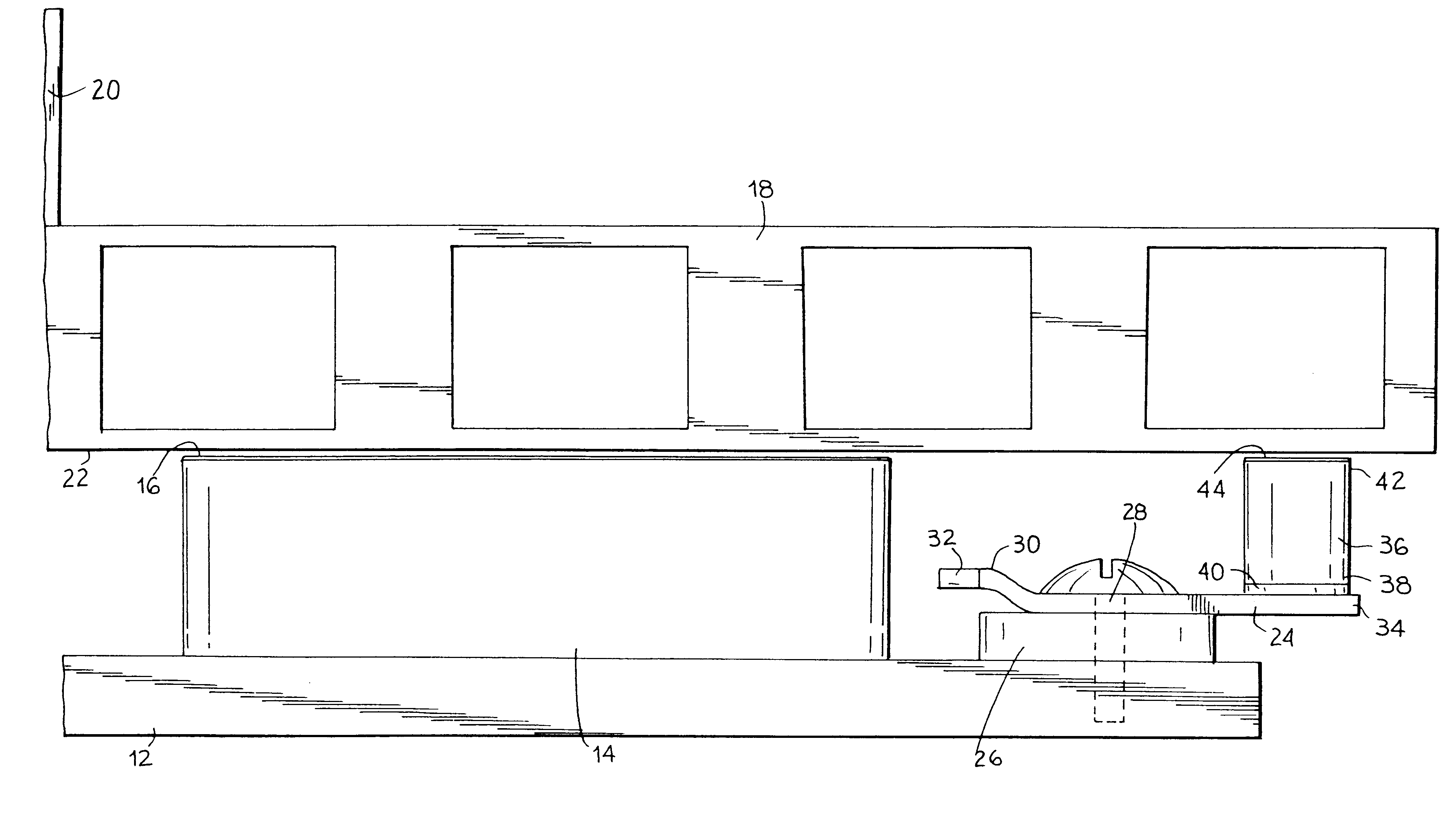
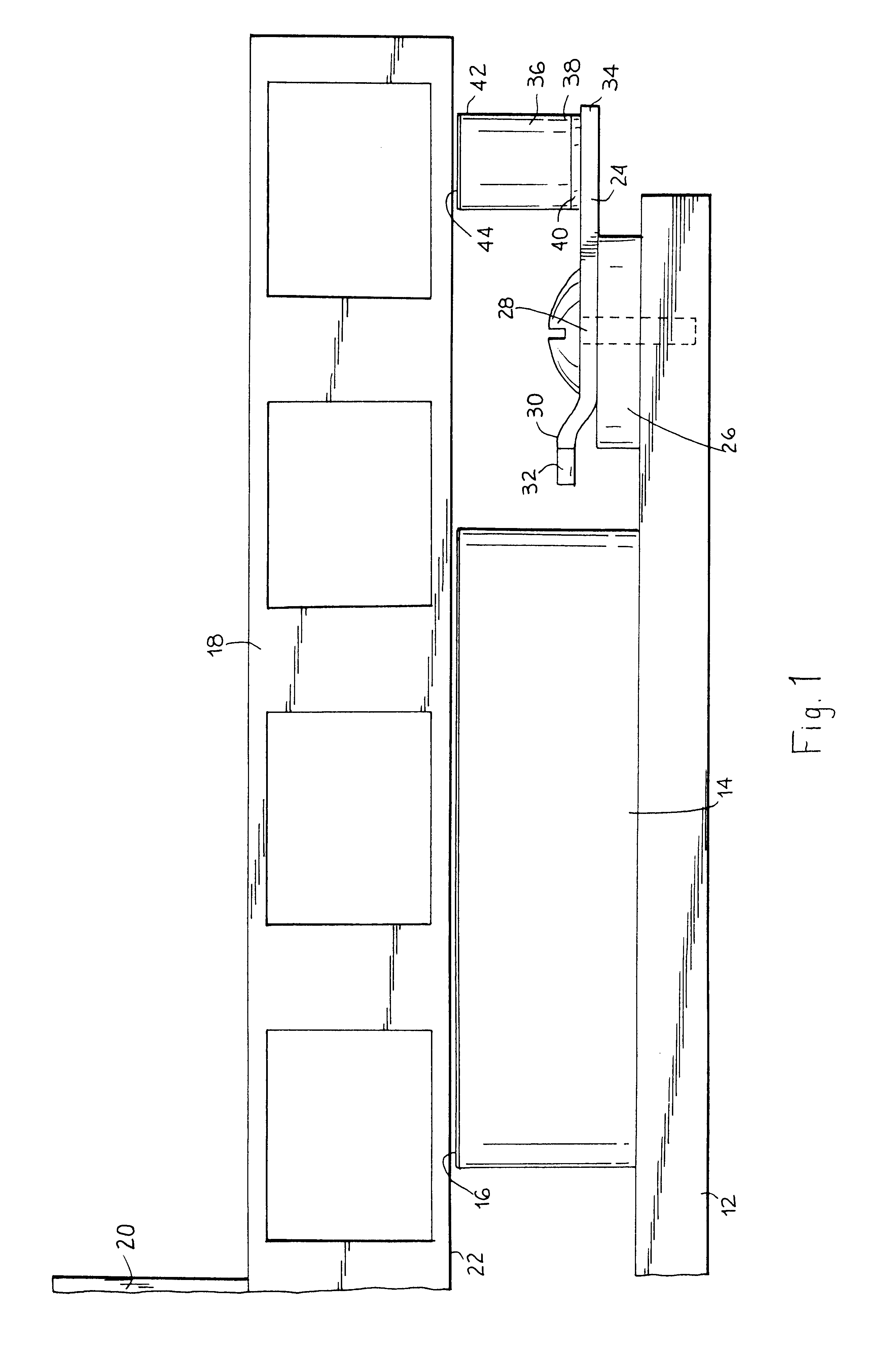
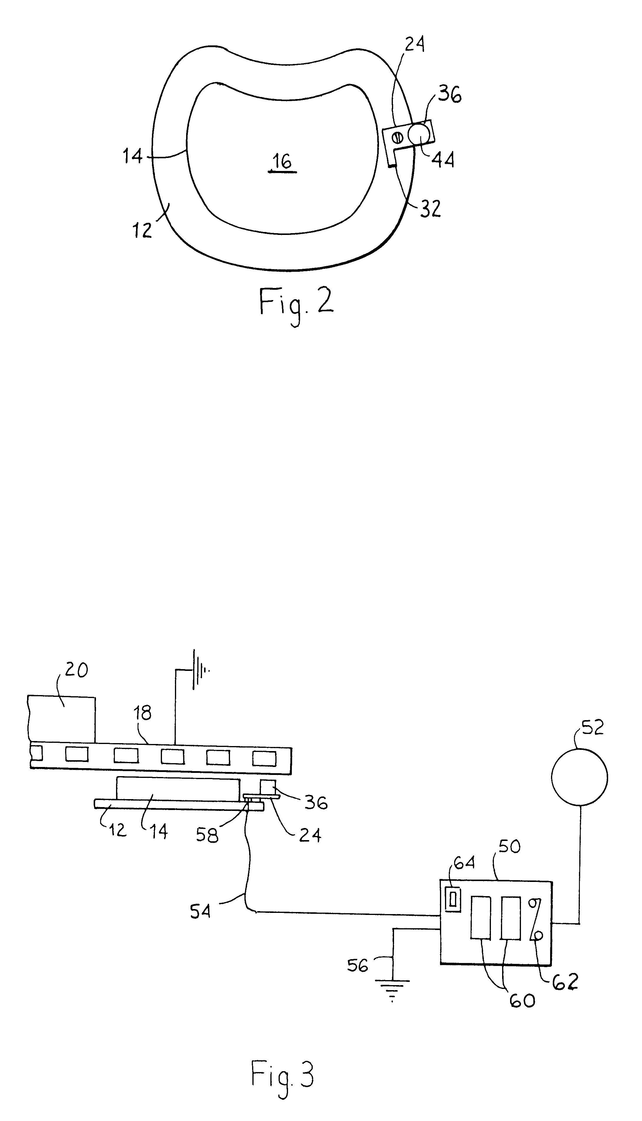
Referring now to FIGS. 1 and 2, a brake pad backing plate 12 supports a brake pad 14. The brake pad backing plate fits into a caliper (not shown) in a conventional manner. The brake pad has a contact or brake surface 16 for pressing against a brake rotor 18. The rotor 18 is attached to and rotates with a wheel hub 20. When a brake mechanism (not shown) moves the support plate and brake pad toward the rotor in response to a vehicle operator pushing on, for example, a brake pedal, the brake pad brake surface 16 applies a rubbing force on a face 22 of the rotor 18. This slows and stops rotation of the wheel hub and movement of the vehicle. The frictional engagement of the rotor face 22 and the brake pad brake surface 16 causes a gradual wearing away of the brake pad, which is made of a softer metal than the rotor.

The present invention comprises a brake pad wear sensor mounted on the backing or support plate 12 on the same side of the plate as the pad 14, adjacent an edge or side of the...


PUM


Abstract

A sensor is attached to a backing plate of a brake pad. The sensor comprises a metal arm extending to one side of the brake pad. The metal arm is electrically insulated from the backing plate. A tab made from a dielectric material projects from a free end of the arm in the same direction that the brake pad extends from the backing plate. The tab is bonded to the arm by an electrically conductive paste. The tab has a wear face spaced from the backing plate the same distance as a brake surface of the brake pad. When a brake is applied by a vehicle operator, both the brake pad brake surface and the tab wear face frictionally engage a brake rotor fixed to a wheel hub. The dielectric material is selected so the tab wears at the same rate as the brake pad. A lead wire connected to the arm enables the capacitance of the tab to be measured by a grounded capacitance meter when the brake is applied. The capacitance changes as the dielectric material wears away. The capacitance is used to indicate the remaining amount of brake pad life on a digital readout.

Description

1. Field of the InventionThe invention is directed in general to vehicle brake pad wear sensors and more specifically to a sensor that is able to measure and display the actual amount of wear left on a brake pad at any given time.2. Discussion of Related ArtTypical brake pad wear sensors use a simple electrical contact to switch on a warning indicator. When the contact is exposed to an electrically grounded brake rotor or drum after a certain amount of wear on the pad, a circuit is closed and current flows to a warning light. Other types of sensors sound an acoustic alarm when a portion of the sensor rubs against the drum or rotor after the brake pad wears a set amount. These warning devices do not indicate the amount of wear left on the brake pads, only that the pads need to be replaced. Because an uncertainty of when brake pad failure will actually occur exists, the designed brake pad life may be cut short due to premature brake pad replacement. In addition, the harsh environment ...

Claims


Application Information

Patent Timeline
Patent Type & Authority Patents(United States)
IPC IPC(8): B60T17/18B60T17/22F16D66/00F16D66/02
CPCB60T17/221F16D66/027
Inventor GRONOWICZ, JR., WILLIAM
Owner YAZAKI NORTH AMERICA
Why Eureka
Try Eureka