Digital-control Colpitts oscillator circuit

a digital control and oscillator technology, applied in the field of digital control oscillator circuits, can solve the problems that the capacitance does not always guarantee the sustenance of stable oscillation

Inactive Publication Date: 2001-10-16
NEC ELECTRONICS CORP
View PDF4 Cites 26 Cited by
  • Summary
  • Abstract
  • Description
  • Claims
  • Application Information

AI Technical Summary

Problems solved by technology

However, an arbitrary change of the equivalent capacitance does not always guarantee sustention of a stable oscillation.

Method used


Image

  • Digital-control Colpitts oscillator circuit
  • Digital-control Colpitts oscillator circuit
  • Digital-control Colpitts oscillator circuit

Examples


first embodiment

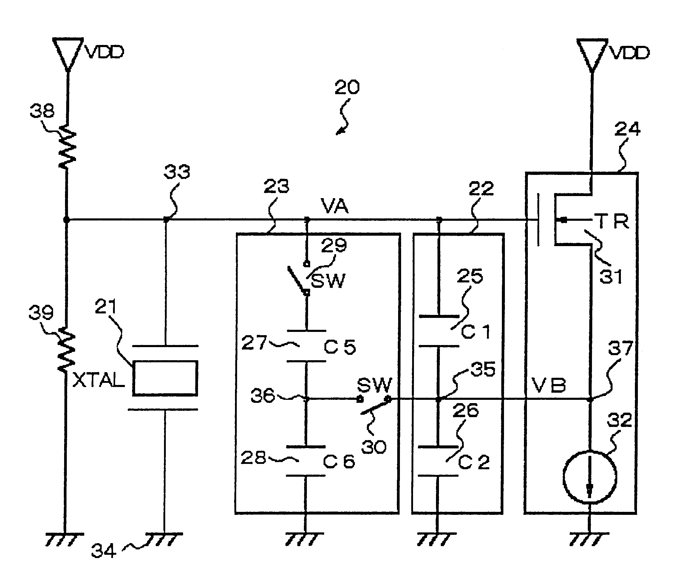
FIG. 3 represents a digital-control Colpitts oscillator circuit of the present invention.

The Colpitts oscillator circuit has a parallel-resonance tank circuit made up of crystal oscillator 21, a first capacitor circuit 22 and a second capacitor circuit 23 connected in parallel. The tank circuit is connected between gate line 33 and the ground potential

The Colpitts oscillator circuit is provided with a source-follower circuit 24 made up of an N-MOS transistor 31 with a source thereof connected with a constant-current source 32.

First capacitor circuit 22 has two voltage-dividing capacitors 25 and 26 connected in series with their common connection 35 connected to output 37 of source follower circuit 24. Both end electrodes of the serially connected capacitors 25 and 26 are connected to gate line 33 and the ground potential, respectively.

First capacitor circuit 22 acts as a main load capacitor (a main resonance capacitor). Capacitors 25 and 26 have capacitances C1 and C2, respectively,...

second embodiment

FIG. 7 represents the digital-control Colpitts oscillator circuit according to the present invention.

In this embodiment, the capacitors are, as a whole, configured as a matrix of elemental capacitors with 2 rows and a plural number n+1 of columns. Two elemental capacitors in each column j (j=0,1, 2, . . . n) are connected in series and the ratio of the capacitance of the 1j elemental capacitor (the elemental capacitor corresponding to the 1j element of the matrix) to the capacitance of the 2j elemental capacitor is prescribed so that a stable oscillation can be sustained.

In addition, a first switch 29-j (j=0, 1, . . . n) and a second switch 30-j are allotted to each j of said columns. Each of the elemental capacitors 27-j allocated to the first row is connected to the gate of transistor 31 through first switch 29-j, and the junction of the two elemental capacitors 27-j and 28-j allocated to each column j is connected to the output of transistor 31 through second switch 30-j. First s...


PUM


Abstract

The Colpitts circuit is configured so that an equivalent capacitance of the voltage-dividing first and second capacitors connected in series through the output of the transistor amplifier is variable under the condition that the ratio of the capacitance of the first capacitor to that of the second capacitor is kept unchanged at a prescribed value. The first and second capacitors are, as a whole, configured as a matrix of elemental capacitors with 2 rows and a plural number n of columns, an array of the elemental capacitors in the first row being allotted to the first capacitor and an array of the elemental capacitors in the second row being allotted to the second capacitor. Two elemental capacitors in each column j (j=1, 2, . . . n) are connected in series and the ratio of the capacitance of the elemental capacitor corresponding to the 1j element of the matrix to the capacitance of the elemental capacitor corresponding to the 2j element has the prescribed value. The Colpitts circuit further has a first switch and a second switch allotted to each of the columns. Each of the elemental capacitors allocated to the first row is connected to the control electrode of the transistor amplifier through the first switch, and the junction of the two elemental capacitors allocated to each column is connected to the output of said transistor amplifier through the second switch. The first and second switches are operated synchronously for every column.

Description

1. Field of the InventionThe present invention relates to a digital-control oscillator circuit provided with an oscillator element and capacitor element, capable of changing the oscillation frequency by changing the capacitance of the load capacitor through a digital signal.2. Description of the Related ArtAn oscillator circuit employing an oscillator element such as a quartz oscillator or a ceramic oscillator provides an oscillation frequency of a high accuracy and a high stability. The oscillator element needs a load. A capacitive element is commonly employed for the load. A change in a capacitance of the capacitive element (hereinafter, referred to as a load capacitor) causes a change in an oscillation frequency of the oscillator circuit.Oscillator circuits, even when produced in a settled manufacturing process, sometimes have a fluctuation in the oscillation frequency. When the fluctuation goes beyond a tolerance range, the oscillation frequency is adjusted by varying the capaci...

Claims


Application Information

Patent Timeline
Patent Type & Authority Patents(United States)
IPC IPC(8): H03B5/36H03B1/00H03B5/32
CPCH03B5/364H03B2201/025H03J2200/10
Inventor TAKAHASHI, YUTAKANAKAMURA, KOUJI
Owner NEC ELECTRONICS CORP
Why Eureka
Try Eureka