Method for leak testing and leak testing apparatus

a leakage testing and leakage technology, applied in the field of leakage testing methods and apparatuses, can solve the problems of increasing the surrounding pressure, necessitating considerable additional expenditure, and not enabling detection of very small leakag

Inactive Publication Date: 2001-10-23
WILCO AG
View PDF14 Cites 43 Cited by
  • Summary
  • Abstract
  • Description
  • Claims
  • Application Information

AI Technical Summary

Benefits of technology

It is a further object of the present invention to provide such method and apparatus which are rather inexpensive with respect to electronic and further equipment, and which thus allow for very economic testing.
Preferred embodiments of the inventive method and inventive apparatus are disclosed hereinafter. The inventive method and apparatus may preferably be used for leak testing blisters, vials, medical application containers, foodstuff or beverage containers, and tanks. Thereby, it must be pointed out that besides of leak testing of smaller containers, the present invention makes it possible to permanently monitor tightness of the tanks of huge tank plants, as for gasoline, gases etc., e.g. on train or street transports, thereby generating an alarm signal as soon as a leak is detected.

Problems solved by technology

If a leak is provided in an area of the container, wherein air is entrapped, a flow of air out of the container will lead to a rise of the surrounding pressure.
Nevertheless, such an approach necessitates considerable additional expenditure with respect to provision of the impedance measuring arrangement in each test cavity, especially of a multi-cavity in-line inspection machine and does not enable detection of very small leaks far below of one micron and largely independent from container shape and kind of filling good.

Method used


Image

  • Method for leak testing and leak testing apparatus
  • Method for leak testing and leak testing apparatus
  • Method for leak testing and leak testing apparatus

Examples


Embodiment Construction

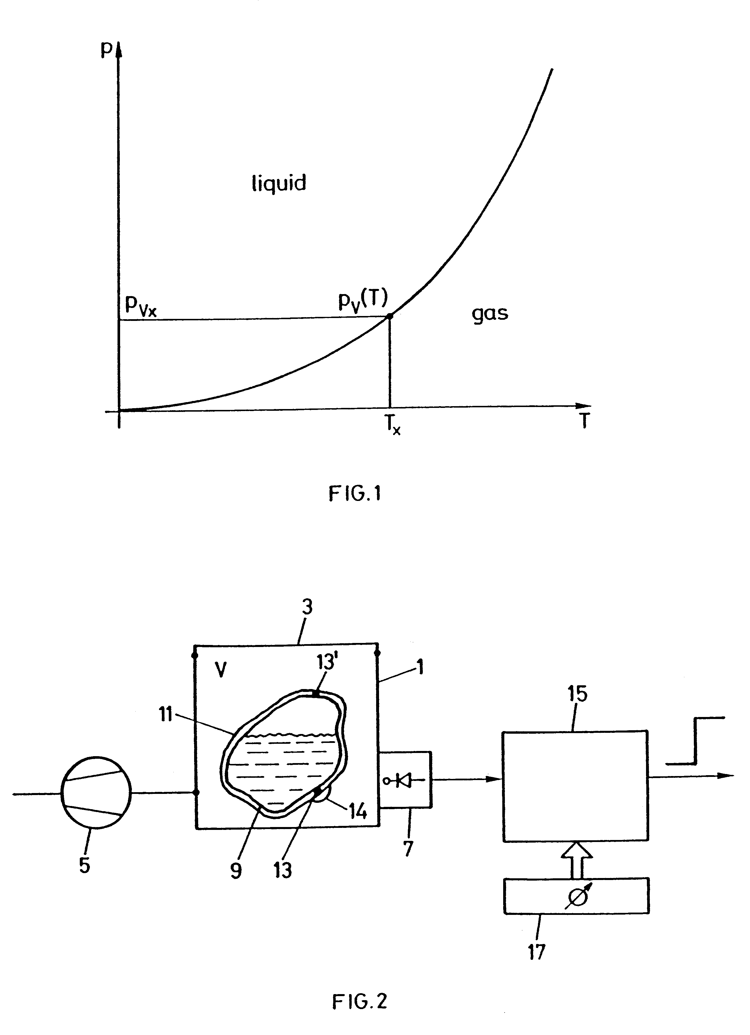
In FIG. 1 there is qualitatively shown the course of vapour pressure p.sub.v (T) in the pressure versus temperature diagram. At a predetermined temperature T.sub.x a liquid starts to evaporate when the respective vapour pressure p.sub.vx is reached. Above the vapour pressure course the material is liquid, below the material is gaseous.

According to FIG. 2 an inventive apparatus comprises a test cavity 1 with a sealingly closable cover 3. A vacuum pump 5 connected to the test cavity 1 which may be a drag pump or a rotational piston valve pump or a diffusion pump or a turbo vacuum pump as a turbo molecular pump. This depends on the degree of vacuum which shall be established within cavity 1. Further, there is provided a vacuum pressure sensor 7 as e.g. a Pirani sensor, which measures the pressure prevailing in the test cavity 1. At least one closed container 9, which is filled at least to some extent with a filling product containing at least one liquid component is introduced through ...


PUM

PropertyMeasurementUnit
temperatureaaaaaaaaaa
vapour pressureaaaaaaaaaa

Abstract

For leak testing closed containers (9) which are filled with a filling product containing at least one liquid component the container is introduced in a test cavity (1) which is evacuated at least down to vapor pressure of that liquid component. The pressure in the surrounding of the container (9) and thus within test cavity (1) is monitored. Monitoring is performed by a vacuum pressure sensor (7), whereas lowering pressure surrounding the container (9) is performed by a vacuum pump (5). Leakage is detected by monitoring a pressure change in the surrounding of the container which is due to evaporation of liquid emerging from a leak and being evaporated in the low pressure surrounding.

Description

The present invention is generically directed on a technique for leak testing closed and filled containers, whereby the filling material comprises at least one liquid component.Leak testing techniques according to which closed containers are introduced in a test cavity which, after having sealingly been closed, is lowered in pressure by a suctioning pump are known. If the container is not leaking, then once a predetermined pressure has been reached in the test cavity and thus in the surrounding of a container to be tested, this pressure will be kept substantially constant. If a leak is provided in an area of the container, wherein air is entrapped, a flow of air out of the container will lead to a rise of the surrounding pressure. If a leak is present in the area of the container where filling good is entrapped, the question whether such leak will lead to a significant rise of the surrounding pressure is largely dependent on the kind of filling good as of its viscosity, whether soli...

Claims


Application Information

Patent Timeline
Patent Type & Authority Patents(United States)
IPC IPC(8): G01M3/32G08B21/20G08B21/00
CPCG01M3/3281G01M3/329G08B21/20Y10T29/49771Y10T29/53022B65B3/04G01M3/04G01M3/22G01M3/226G01M3/3263
Inventor LEHMANN, MARTIN
Owner WILCO AG
Why Eureka
Try Eureka