
Metal-air fuel cell battery systems employing means for discharging and recharging metal-fuel cards

a fuel cell battery and metal-air technology, applied in the direction of primary cell maintenance/service, cell components, secondary cell maintenance/maintenance, etc., can solve the problem that metal-fuel in the form of tape may not be desirabl

Inactive Publication Date: 2001-10-23
REVEO
View PDF79 Cites 28 Cited by
  • Summary
  • Abstract
  • Description
  • Claims
  • Application Information

AI Technical Summary

Benefits of technology

Accordingly, a primary object of the present invention is to provide an improved method and apparatus of discharging and recharging metal-air fuel cell batteries (FCB) in a manner which avoids the shortcomings and drawbacks of prior art technologies.
Another object of the present invention is to provide an improved method and apparatus for electrochemically generating electrical power across an electrical load by discharging metal-air fuel cell batteries in a manner which allows for optimal recharging of the same during recharging cycles.

Problems solved by technology

In practice, however, there are many contemplated applications where metal-fuel in the form of tape may not be desirable by virtue of the fact that special mechanisms are typically required to transport the metal-fuel tape through the system, during discharging and recharging modes of operation.

Method used


Image

  • Metal-air fuel cell battery systems employing means for discharging and recharging metal-fuel cards
  • Metal-air fuel cell battery systems employing means for discharging and recharging metal-fuel cards
  • Metal-air fuel cell battery systems employing means for discharging and recharging metal-fuel cards

Examples


Embodiment Construction

Of the Present Invention should be read in conjunction with the accompanying Drawings, wherein:

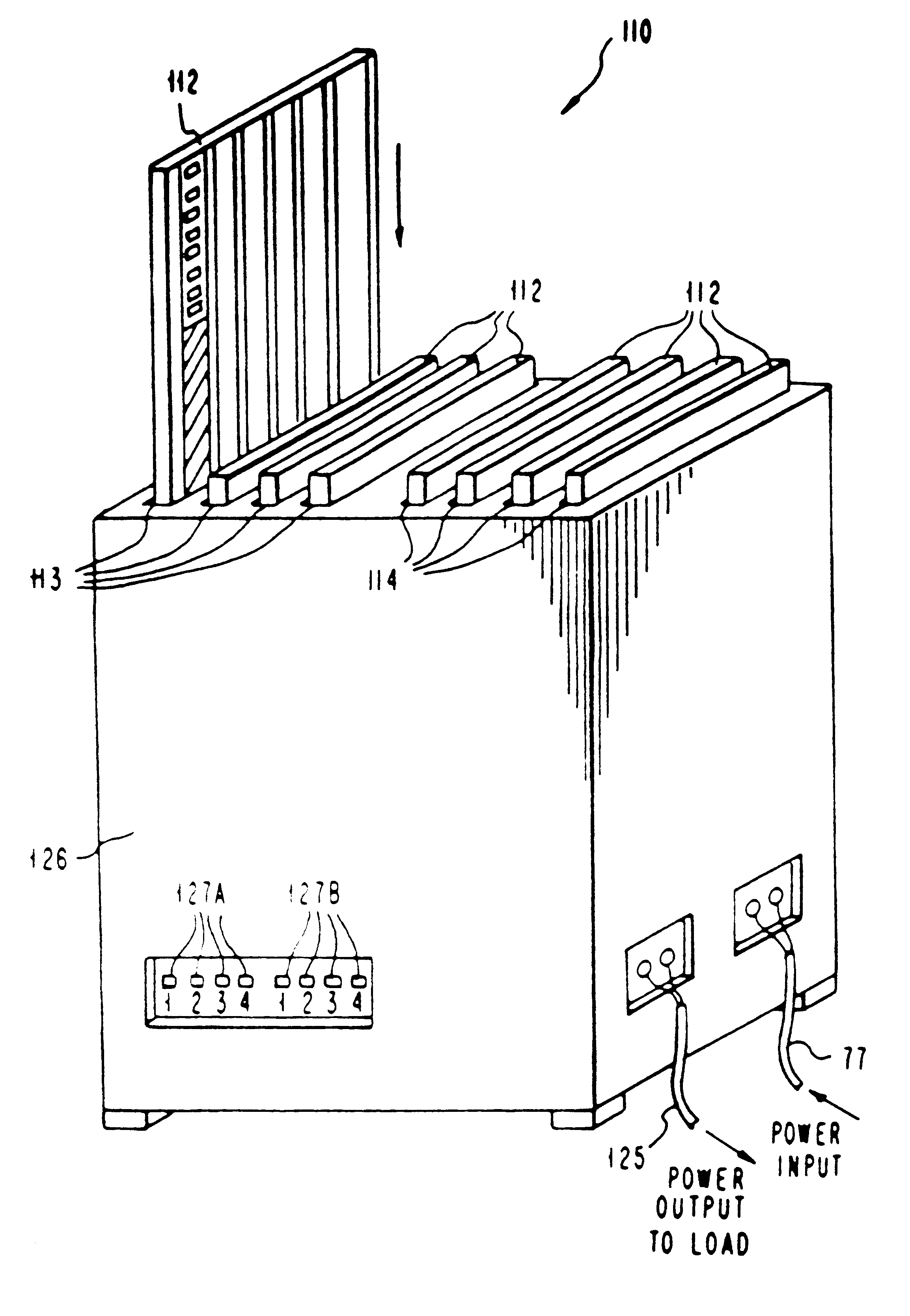
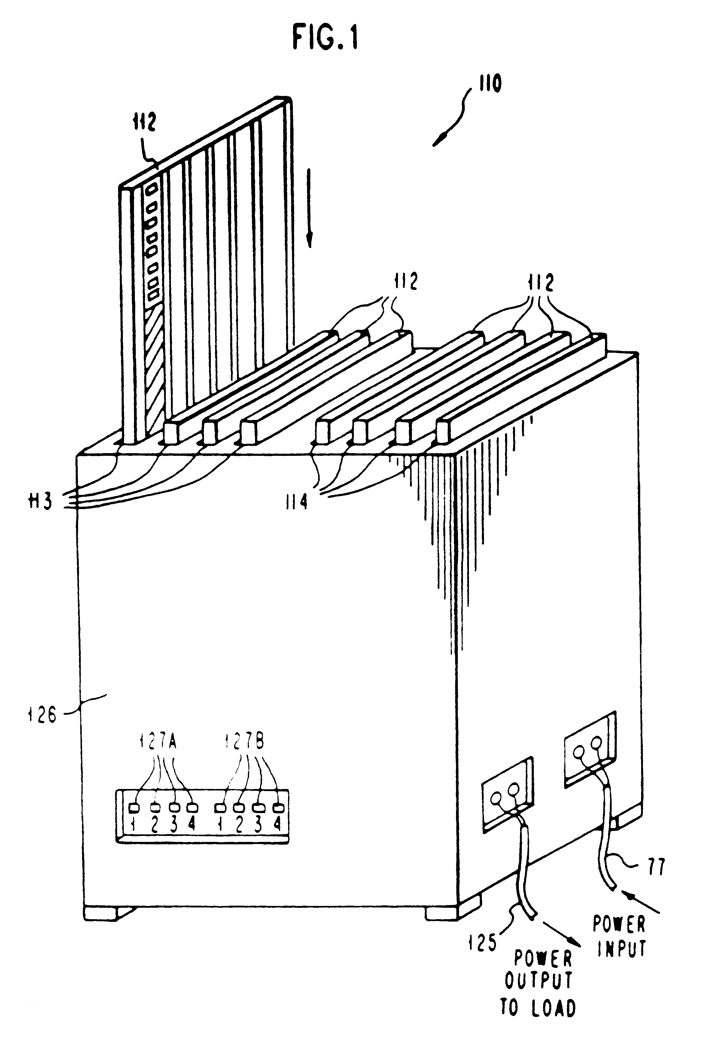
FIG. 1 is a schematic diagram showing a first illustrative embodiment of the metal-air FCB system of the present invention, wherein a first plurality of recharged metal-fuel cards (or sheets) are semi-manually loaded into the discharging bay of its Metal-Fuel Card Discharging Subsystem, while a second plurality of discharged metal-fuel cards (or sheets) are semi-manually loaded into the recharging bay of its Metal-Fuel Card Recharging Subsystem;

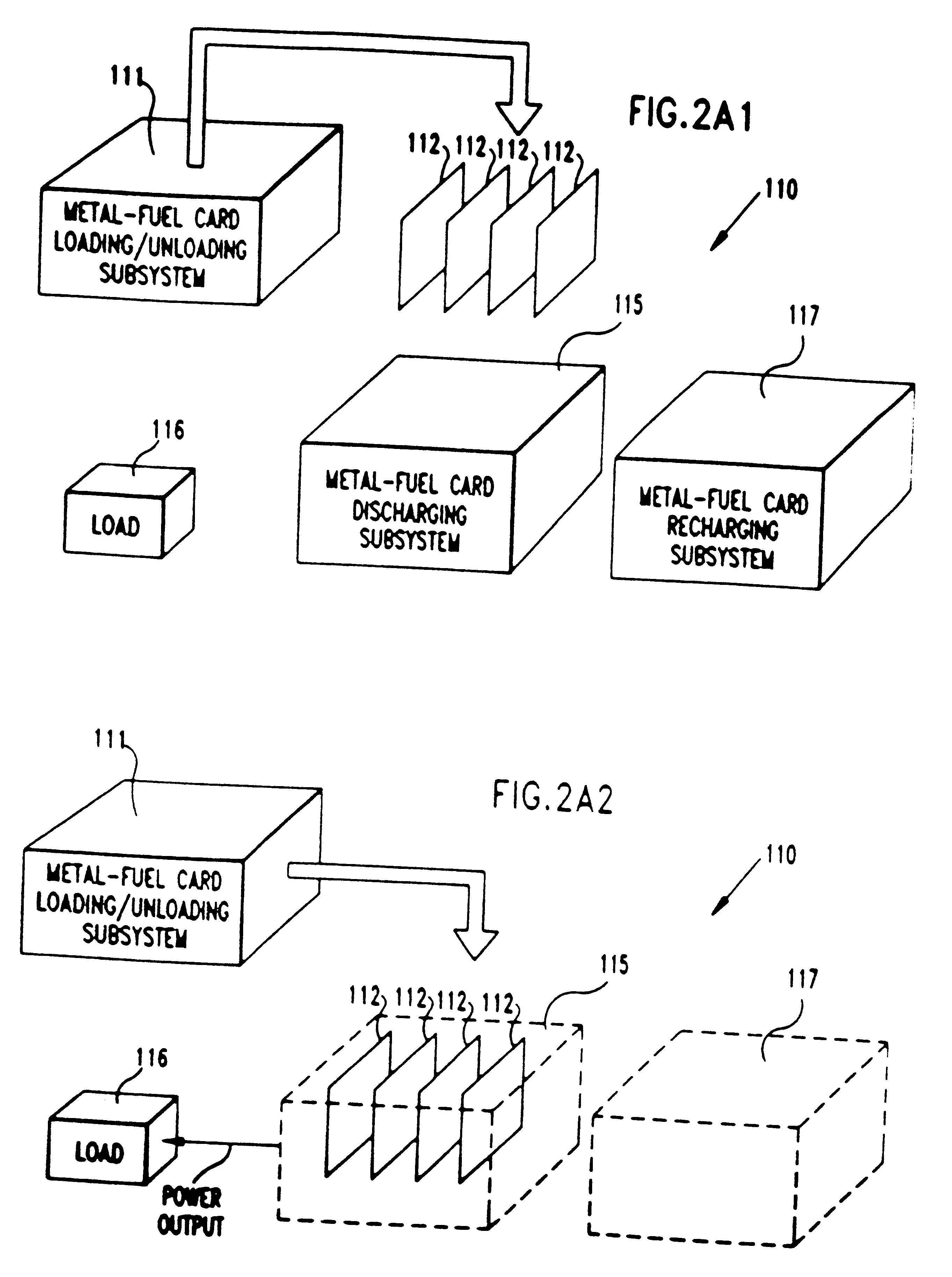
FIG. 2A1 is a generalized schematic representation of the metal-air FCB system of FIG. 1, wherein metal-fuel cards are shown about-to-be inserted within the discharging bays of the Metal-Fuel Card Discharging Subsystem, and not within the recharging bays of the Metal-Fuel Card Recharging Subsystem;

FIG. 2A2 is a generalized schematic representation of the metal-air FCB system of FIG. 1, wherein metal-fuel cards of FIG. 1 are shown loaded within the d...


PUM


Abstract

Disclosed are various types of metal-air FCB-based systems comprising a Metal-Fuel Transport Subsystem, a Metal-Fuel Discharging Subsystem, and a Metal-Fuel Recharging Subsystem. The function of the Metal-Fuel Transport Subsystem is to transport metal-fuel cards or sheets to the Metal-Fuel Discharge Subsystem, or the Metal-Fuel Recharge Subsystem, depending on the mode of the system selected. When transported to or through the Metal-Fuel Discharge Subsystem, each metal-fuel card is discharged by (i.e. electro-chemically reaction with) one or more discharging heads in order produce electrical power across an electrical load connected to the subsystem while H2O and O2 are consumed at the cathode-electrolyte interface during the electro-chemical reaction. When transported to or through the Metal-Fuel Recharging Subsystem, discharged metal-fuel is recharged by one or more recharging heads in order to convert the oxidized metal-fuel material into its source metal material suitable for reuse in power discharging operations, while O2 is released at the cathode-electrolyte interface during the electro-chemical reaction. In the illustrative embodiments, various forms of metal fuel cards can be discharged and recharged in an efficient manner to satisfy a broad range of electrical loading conditions.

Description

FIELD OF THE INVENTIONThe present invention relates to improved methods and systems for optimally discharging metal-air fuel cell battery (FCB) systems and devices, as well as improved methods and systems for optimally recharging the same in a quick and efficient manner.DESCRIPTION OF THE PRIOR ARTIn copending U.S. application Ser. No. 08 / 944,507, Applicant discloses several types of novel metal-air fuel cell battery (FCB) systems. During power generation, metal-fuel tape is transported over a stationary cathode structure in the presence of an ionically-conducting medium, such as an electrolyte-impregnated gel. In accordance with well known principles of electro-chemistry, the transported metal-fuel tape is oxidized as electrical power is produced from the system.Metal-air FCB systems of the type disclosed in U.S. application Ser. No. 08 / 944,507 have numerous advantages over prior art electro-chemical discharging devices. For example, one advantage is the generation of electrical po...

Claims


Application Information

Patent Timeline
IPC IPC(8): H01M2/02H01M10/48H01M12/06H01M10/42H01M12/00H01M10/46H01M8/04H01M2/12H01M4/00H01M4/02H01M4/70
CPCH01M6/5011H01M8/184H01M8/186H01M8/22H01M10/4214H01M12/06H01M12/08H02J7/00H01M4/42H01M2/1673Y02E60/528H01M4/8605H01M10/44H01M2004/024H01M2300/0085H01M50/46Y02E60/10Y02E60/50
Inventor FARIS, SADEG M.TSAI, TSEPIN
Owner REVEO
Learn More