Method for starting a power loom

a technology of power looms and looms, which is applied in the direction of looms, dynamo-electric machines, weaving, etc., can solve the problems of so-called start-up faults in fabric, enlarged spacing between neighboring threads, and low instantaneous rotation speed of the loom at the first reed beat-up

Inactive Publication Date: 2001-10-23
LINDAUER DORNIER GMBH
View PDF10 Cites 19 Cited by
  • Summary
  • Abstract
  • Description
  • Claims
  • Application Information

AI Technical Summary

Problems solved by technology

It can happen during such a coupling operation that the main loom drive shaft is completely coupled to the power drive before the first reed beat-up, but that the instantaneous rotational speed of the loom is too low at the first reed beat-up.
As a result, so-called start-up faults are formed in the fabric.
Such start-up

Method used


Image

  • Method for starting a power loom
  • Method for starting a power loom

Examples


second example embodiment

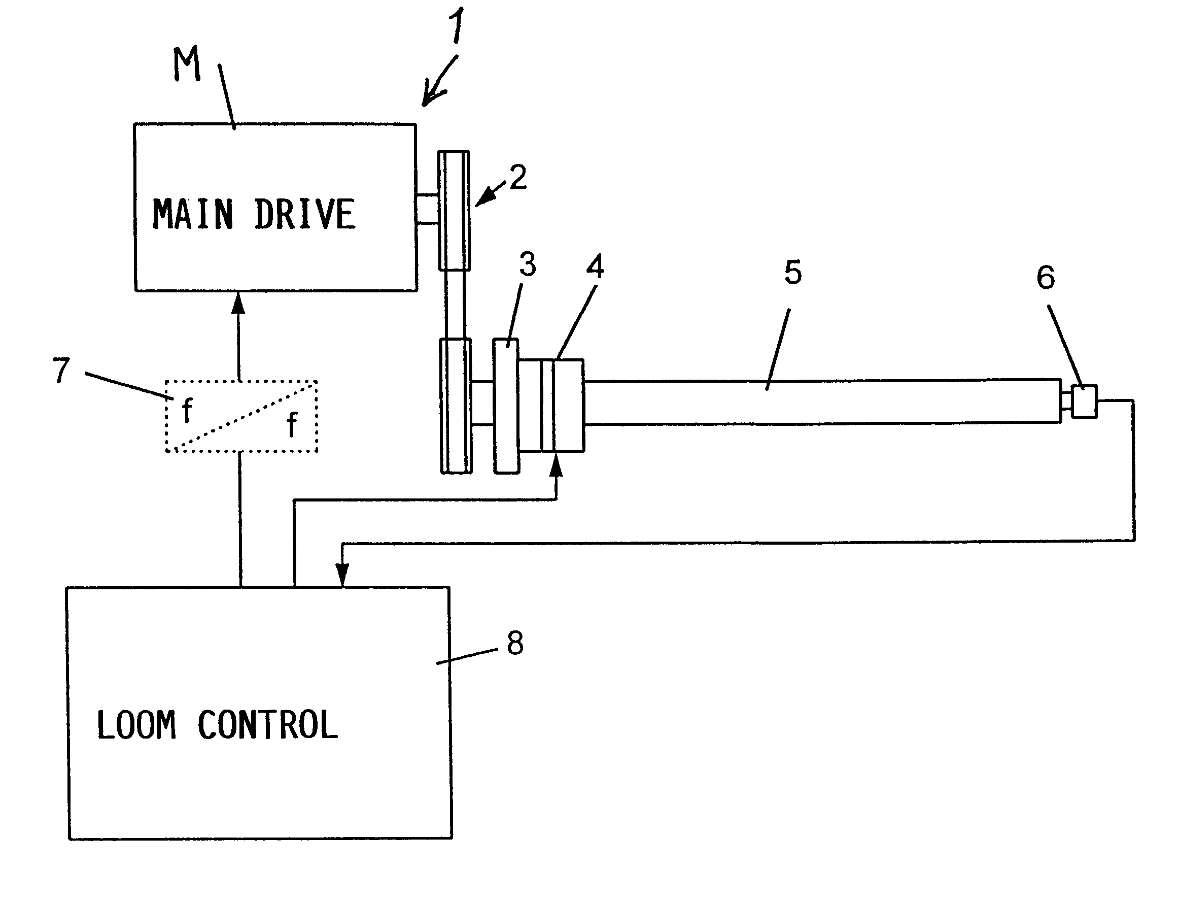
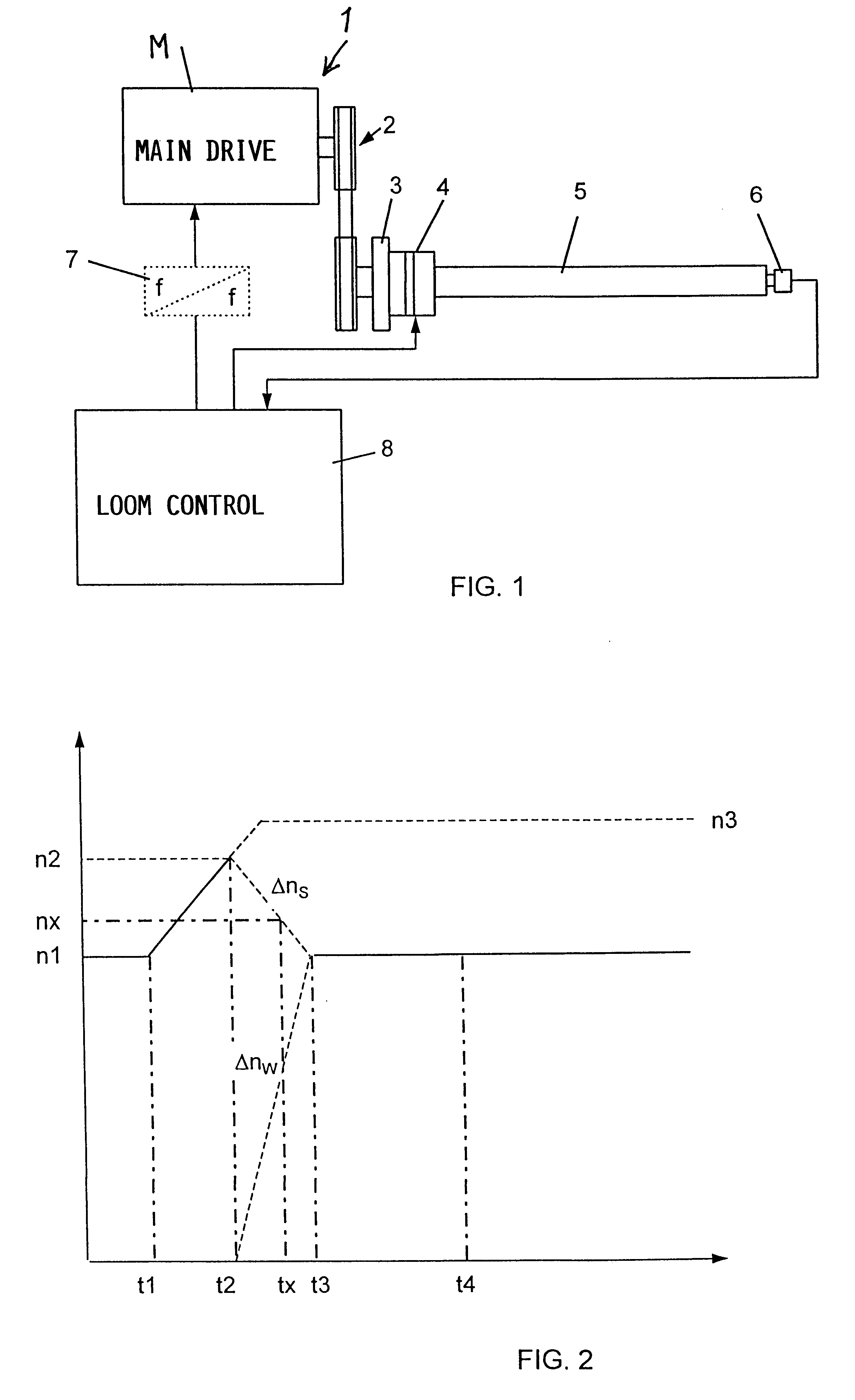
In a second example embodiment according to the inventive method, the main drive 1 for the power loom comprises and is driven by a frequency controlled motor M. A respective rated operating rpm n1 for the flywheel mass 3 is generated by feeding the specified rated frequency f to the motor M through the frequency converter 7.

To start up the loom after eliminating a fault, for example, the loom control 8 feeds a higher operating frequency that is supplied by the frequency converter 7 to the motor M at time t1. This results in an increased rpm of the motor N and, accordingly, the flywheel mass 3 is accelerated from an idle or no-load condition to the respective increased rpm n2. Once the flywheel mass 3 has reached the specified start-up rpm n2, which is the cage at time t2, then the clutch-brake unit 4 is actuated and the flywheel mass 3 is coupled with the main drive shaft 5 of the loom. As shown in FIG. 2, the rpm or rotational speed of the flywheel mass 3 decreases along the dashed...


PUM


Abstract

A main drive shaft of a power loom reaches the rated operating rpm of the loom by the time of the first beat-up of the reed, thus avoiding start-up faults in the fabric. A flywheel mass is accelerated to a start-up rpm that is higher than the rated operating rpm before it is coupled with the main drive shaft. The start-up rpm is determined automatically and iteratively, with ever-increasing accuracy in successive starts of the loom. When the main drive shaft is coupled to the flywheel mass, the flywheel mass rpm decreases simultaneously as the main drive shaft rpm increases from standstill to the operating rpm. The actual main drive shaft rpm is measured at least at the time of the first beat-up and any deviation from the rated operating rpm is evaluated by the loom control. After each start-up, a new data set is generated based on the measured values and is used to calculate an updated or modified flywheel start-up rpm in the next start-up operation so that the main drive shaft more accurately reaches at least the rated operating rpm by the time of the first beat-up of the reed.

Description

PRIORITY CLAIMThis application is based on and claims the priority under 35 U.S.C. .sctn.119 of German Patent Application 199 14 131.2, filed on Mar. 27, 1999, the entire disclosure of which is incorporated herein by reference.The invention relates to a method of starting a power loom equipped with an electric main drive. In such a loom the main drive drives at least one flywheel mass that is coupled to the main drive and is coupled to a main drive shaft by a clutch.BACKGROUND INFORMATIONIt is customary to drive power looms by an electric motor that is connected to an a.c. power supply or a three-phase power supply network. Preferably, pole-switchable or frequency-controlled motors are used. The main power drive is coupled by power transmission means, such as a belt and pulley drive, to a flywheel mass which is coupled to the main drive shaft of the loom, whereby the electric motor drives the flywheel mass. Prior art systems are so constructed that following the switching-on of the ...

Claims


Application Information

Patent Timeline
IPC IPC(8): D03D51/00D03D51/02D03D51/12
CPCD03D51/00D03D51/02D03D51/12D03D51/002D03D51/007
Inventor WAGNER, ARNOMUELLER, HERBERT
Owner LINDAUER DORNIER GMBH
Why Eureka
Try Eureka