Detection method and apparatus for the tip of a chemical mechanical polishing conditioner

Inactive Publication Date: 2014-11-13
KINIK
View PDF20 Cites 1 Cited by
  • Summary
  • Abstract
  • Description
  • Claims
  • Application Information

AI Technical Summary

Benefits of technology

[0026]In summary, according to a detection method and apparatus for the tip of a chemical mechanical polishing conditioner of the present invention, the abrasive particles with a particular protruding height may be marked and detected by providing dyeing method, and the abrasive particles with a particular protruding height may

Problems solved by technology

A person wastes his energy and time on the well-known methods, and the detection results of the well-known methods are still doubtful.
On the other hand, if the abrasive particles with a particular protruding height are present on the chemical mechanical polishing conditioner, the scratches and breakages are not only produced on the polishing pad due to the abrasive particles with a particular protruding height during chemical

Method used


Image

  • Detection method and apparatus for the tip of a chemical mechanical polishing conditioner
  • Detection method and apparatus for the tip of a chemical mechanical polishing conditioner
  • Detection method and apparatus for the tip of a chemical mechanical polishing conditioner

Examples


example 1

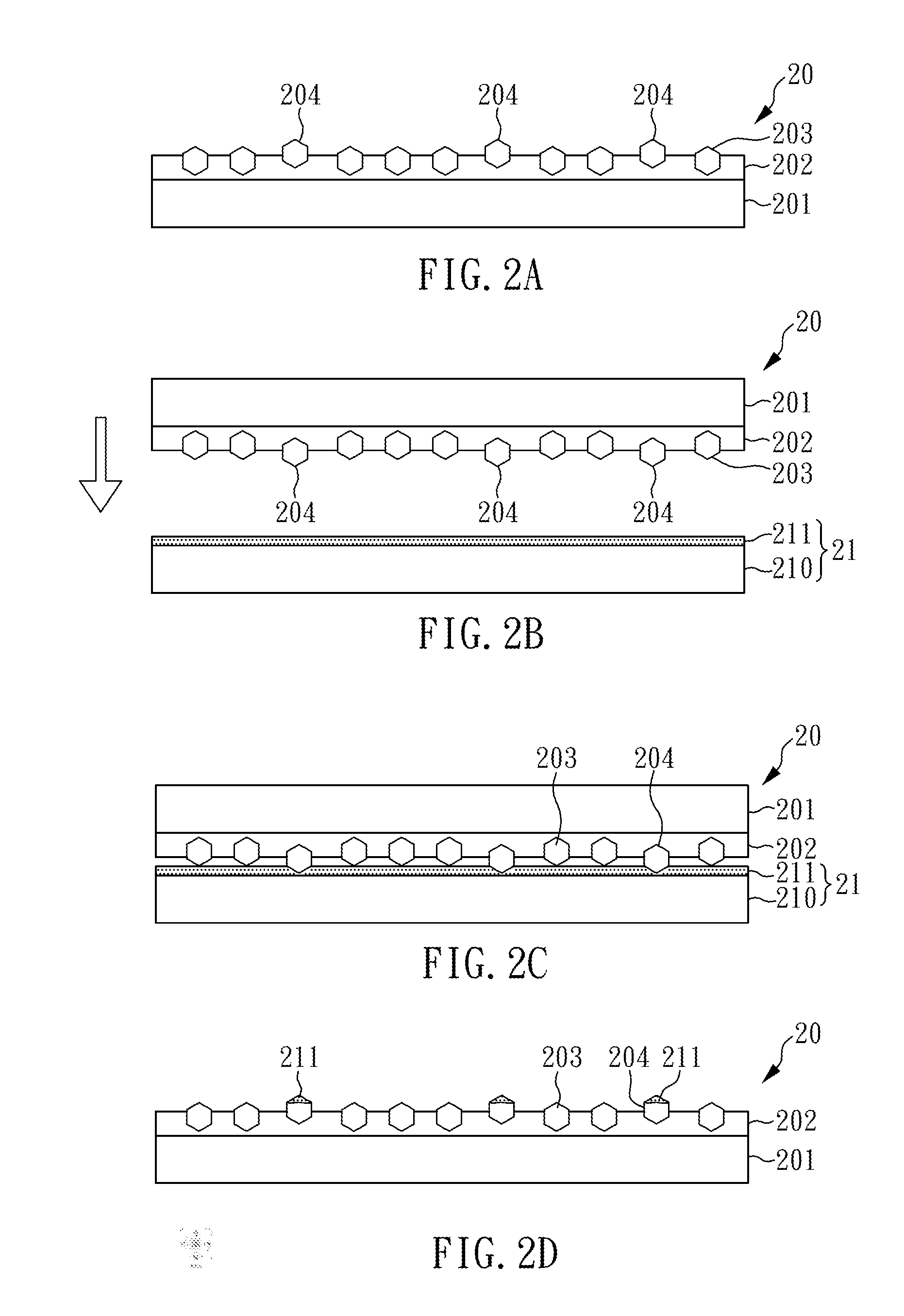
[0033]Please refer to FIGS. 2A to 2D, a flow diagram of detection method for the tip of a chemical mechanical polishing conditioner of example 1 of the present invention is shown. First, as shown in FIG. 2A, a chemical mechanical polishing conditioner 20 is provided, which comprises a substrate 201 made of stainless steel, a binding layer made of nickel-based metallic brazing material, and a plurality of abrasive particles 203 fixed on the substrate 201 by the binding layer 202; wherein the abrasive particles may have a particle size of 200 μm, and an installation method of abrasive particles 203 may be a known diamond distribution technique, for example, template distribution. The spacing and arrangement of the abrasive particles 203 may be controlled by the template (not shown in figure). Besides, a few of abrasive particles 204 with a particular protruding height are present on the chemical mechanical polishing conditioner 20 simultaneously.

[0034]Further, as shown in FIG. 2 B, a ...

example 2

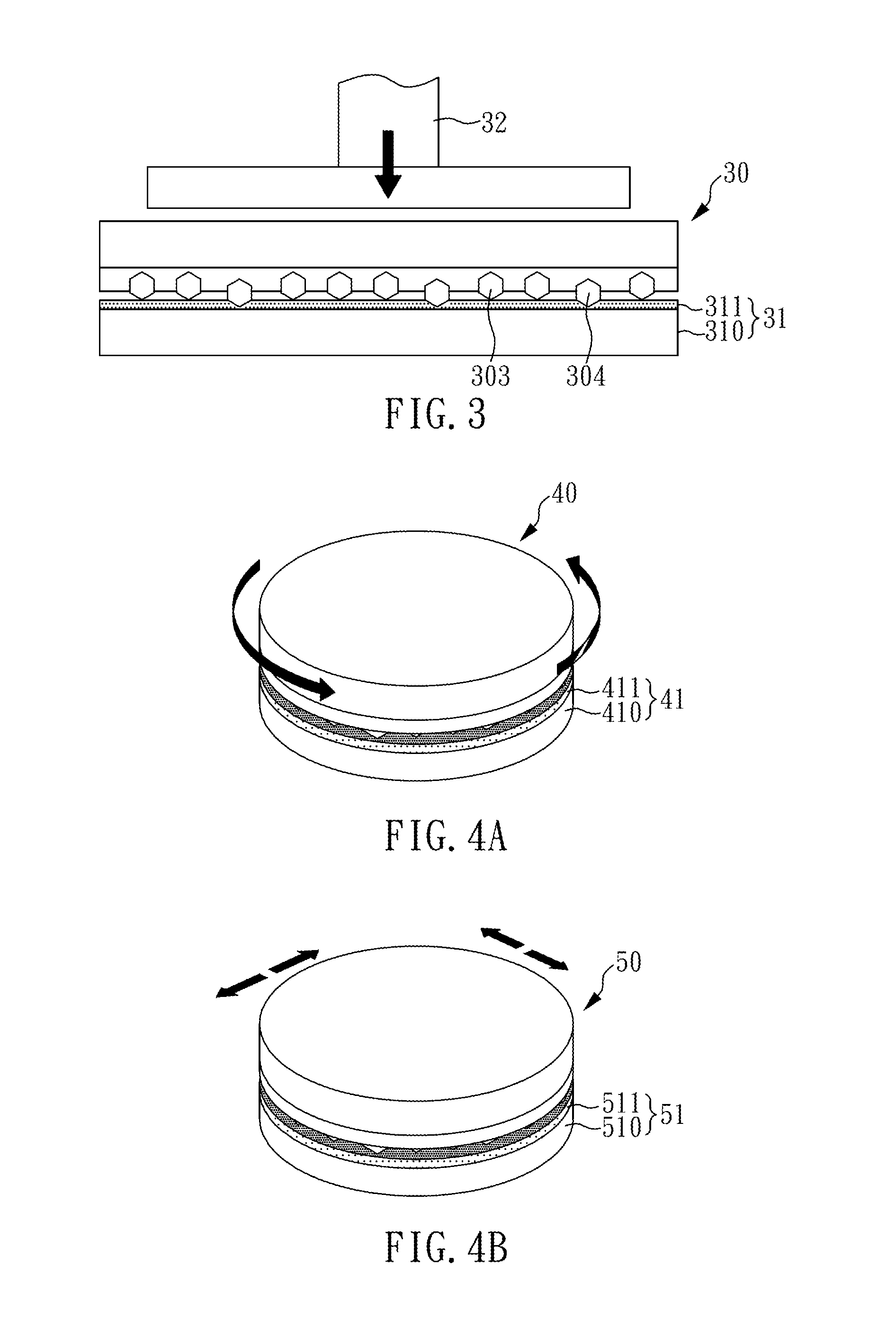
[0039]Please refer to FIGS. 3, a flow diagram of detection method for the tip of a chemical mechanical polishing conditioner of example 1 of the present invention is shown. The detection methods for the tip of a chemical mechanical polishing conditioner of Example 2 is substantially the same as the above Example 1, but the differences are as following. In the detection methods for the tip of a chemical mechanical polishing conditioner of Example 1, the action mode of the downward force is the gravity formed by itself weight of the chemical mechanical polishing conditioner, but in example 2, the downward force is that an additional downward gravity is applied to the chemical mechanical polishing conditioner. As shown in FIG. 3, the abrasive particles 303 of the chemical mechanical polishing conditioner 30 are toward the dyeing apparatus 31. Further, the dyeing apparatus 31 comprises a dyeing layer 311 and a dyeing platform 310, and a downward force (as shown in direction of arrow of ...

examples 3 and 4

[0040]Please refer to FIGS. 4A and 4B, schematic diagrams of detection method for the tip of a chemical mechanical polishing conditioner of examples 3 and 4 of the present invention are shown. The detection methods for the tip of a chemical mechanical polishing conditioner of Examples 3 and 4 are substantially the same as the above Example 1, but the differences are as following. In the detection methods for the tip of a chemical mechanical polishing conditioner of Example 1, the movement mode of the downward force is that a pressure is applied to a fixed position of the dyeing layer by the chemical mechanical polishing conditioner, but in Examples 3 and 4, the movement mode of the downward force is that a pressure is applied to a non-fixed position of the dyeing layer by the chemical mechanical polishing conditioner.

[0041]As shown in FIG. 4A, in Example 3, the abrasive particles (not shown in figure) on the chemical mechanical polishing conditioner 40 are toward the dyeing apparatu...


PUM


Abstract

The present invention relates to a detection method and apparatus for the tip of the chemical mechanical polishing conditioner, which comprises: providing a dyeing apparatus comprising a dyeing layer; providing a chemical mechanical polishing conditioner comprising a substrate, a binding layer, and a plurality of abrasive particles, the abrasive particles fixed on the substrate by the binding layer; making the abrasive particles of the chemical mechanical polishing conditioner toward the dyeing apparatus and provide a downward force, so that the chemical mechanical polishing conditioner is contacted with the dyeing layer; and separating the chemical mechanical polishing conditioner and the dyeing apparatus, so that the abrasive particles with a particular protruding height form dyeing abrasive particles adhered the dyeing layer on their surface, and the dyeing abrasive particles are determined as a defect of destroying the flatness of chemical mechanical polishing conditioner.

Description

CROSS REFERENCE TO RELATED APPLICATION[0001]This application claims the benefits of the Taiwan Patent Application Serial Number 102116517, filed on May 9, 2013, the subject matter of which is incorporated herein by reference.BACKGROUND OF THE INVENTION[0002]1. Field of the Invention[0003]The present invention relates to a detection method and apparatus for the tip of a chemical mechanical polishing conditioner, and more particularly to a chemical mechanical polishing conditioner which may provide a detection of the abrasive particles with a particular protruding height on the chemical mechanical polishing conditioner by a dyeing method detection.[0004]2. Description of Related Art[0005]Chemical mechanical polishing (CMP) is a common polishing process in various industries, which can be used to grind the surfaces of various articles, including ceramics, silicon, glass, quartz, or a metal chip. In addition, with the rapid development of integrated circuits, chemical mechanical polishi...

Claims


Application Information

Patent Timeline
IPC IPC(8): G01N31/22
CPCG01N31/22B24B49/12B24B49/18B24B53/017
Inventor CHOU, JUI-LINWANG, CHIA CHUNCHIU, CHIA-FENGLIAO, WEN-JEN
Owner KINIK
Why Eureka
Try Eureka