In-vehicle switch mechanism

a switch mechanism and in-vehicle technology, applied in the direction of vehicle operation, rope railway, routes, etc., can solve the problems of head-to-seat and other passenger discomfor

Inactive Publication Date: 2001-10-30
RAYTHEON CO
View PDF64 Cites 28 Cited by
  • Summary
  • Abstract
  • Description
  • Claims
  • Application Information

AI Technical Summary

Benefits of technology

It is a further object of this invention to provide such an improved in-vehicle switch mechanism which is self-aligning whe...

Problems solved by technology

One problem with such mechanisms is that when the vehicle enters an intersection the bilateral guiding is lost and...

Method used


Image

  • In-vehicle switch mechanism
  • In-vehicle switch mechanism
  • In-vehicle switch mechanism

Examples


Embodiment Construction

Other objects, features and advantages will occur to those skilled in the art from the following description of a preferred embodiment and the accompanying drawings, in which:

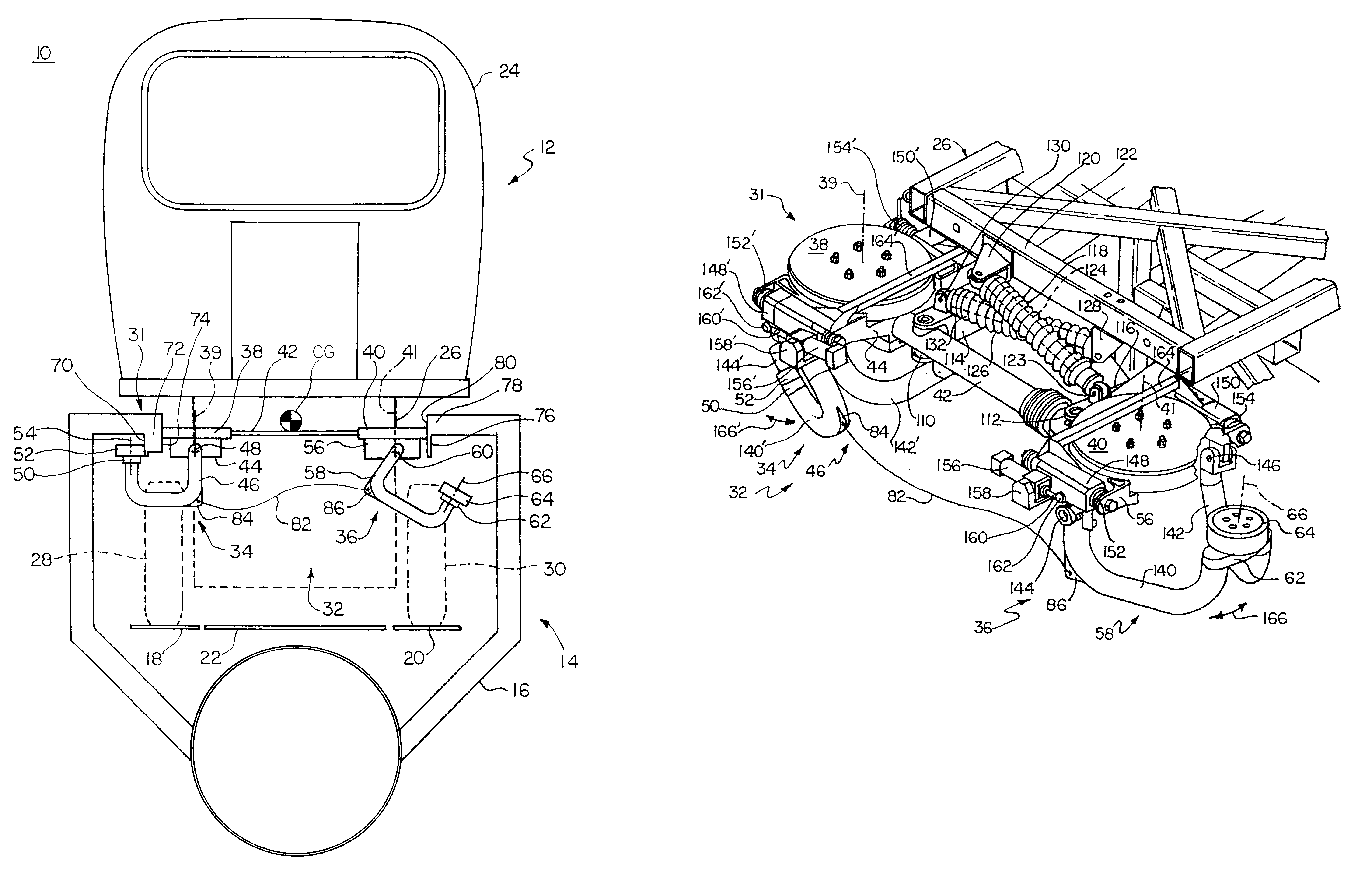
FIG. 1 is a schematic end view of a guided vehicle and guideway of a guided vehicle system using the in-vehicle switch mechanisms according to this invention;

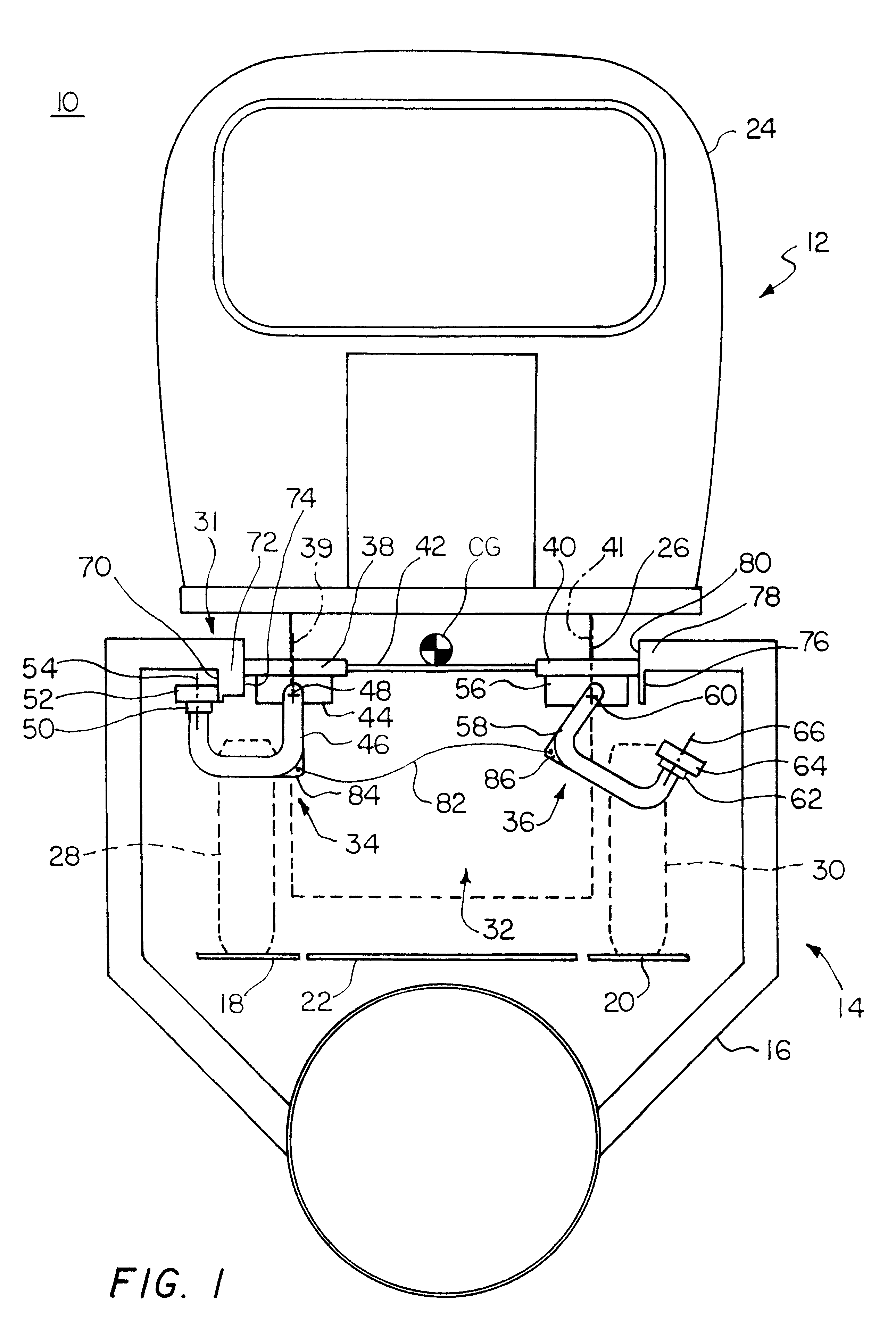
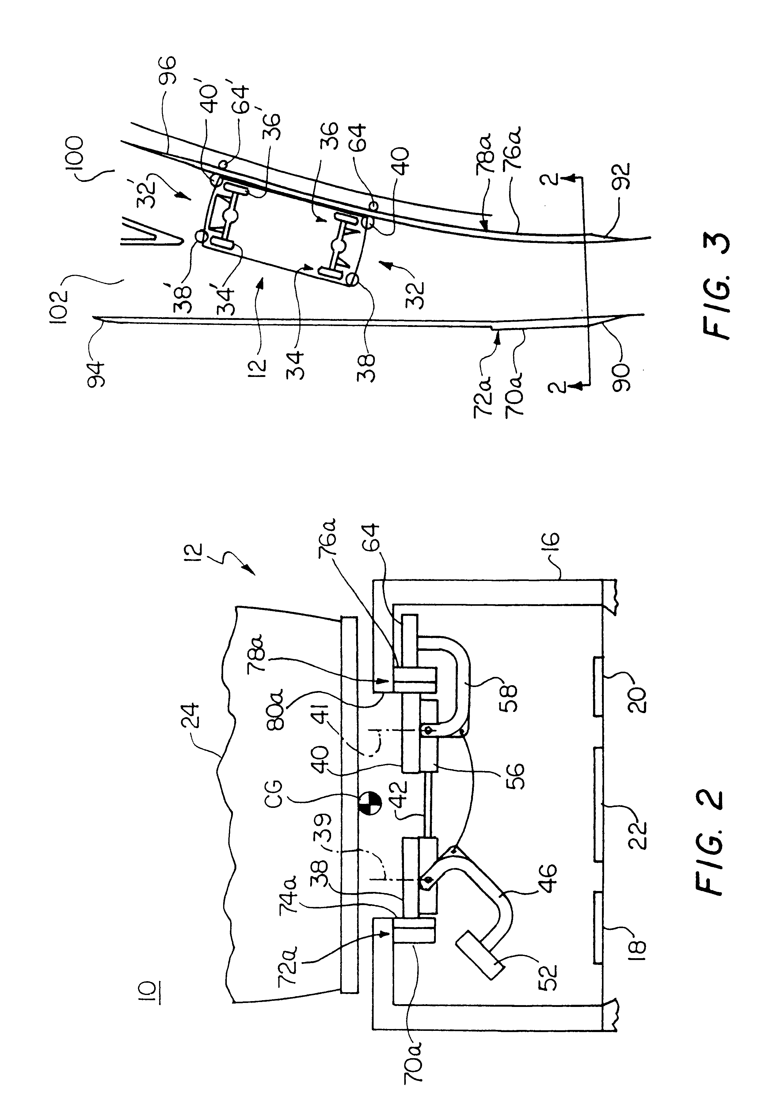
FIG. 2 is a view similar to FIG. 1 with parts removed for clarity showing a lateral suspension system combined with two in-vehicle switch mechanisms, one stowed and one deployed, a section of guideway along line 2--2 of FIG. 3;

FIG. 3 is a top plan view of the guideway of FIG. 2;

FIG. 4 is a three-dimensional view of two in-vehicle switch mechanisms according to this invention, a lateral suspension system and vehicle chassis frame;

FIG. 5 is a diagrammatic front elevational view of the lateral suspension system and in-vehicle switch mechanisms of FIG. 4;

FIG. 6 is a top plan view similar to FIG. 5;

FIG. 7 is an enlarged detailed diagrammatic sectional view of a...


PUM


Abstract

An in-vehicle switch mechanism for guiding a vehicle along a guideway at converging and diverging points of the guide rails in a guided vehicle system includes a support frame; a pivot assembly; a switch arm assembly pivotably mounted at its proximate end to the pivot assembly; a switch wheel rotatably mounted to the switch arm assembly at its distal end; an actuator for moving the switch arm between a deployed position in which the switch wheel engages a guide rail and a stowed position in which the switch wheel is free of the guide rail; and a biasing device interconnected between the support frame and pivot assembly for pre-loading the switch wheel against the guide rail when the switch wheel is deployed as the vehicle approaches the point of divergence; and an in-vehicle switch system which uses such in-vehicle switch mechanisms.

Description

This invention relates to an improved in-vehicle switch mechanism for a guided vehicle.BACKGROUND OF INVENTIONConventional laterally guided vehicles rely on lateral guideways to stabilize and direct them along the guideway. A switching mechanism is used to select one of two pathways when a vehicle approaches an intersection. The guideway itself has no moving parts and switching of the vehicle at diverging and converging points of the guideway is accomplished by forcing the vehicle to adhere to one side of the guideway while approaching a point of divergence with the system. One problem with such mechanisms is that when the vehicle enters an intersection the bilateral guiding is lost and so the vehicle is apt to be less stable and can hunt from side to side causing head-toss and other passenger discomfort.SUMMARY OF INVENTIONIt is therefore an object of this invention to provide an improved in-vehicle switch mechanism and an in-vehicle switch system using such a switch mechanism.It i...

Claims


Application Information

Patent Timeline
IPC IPC(8): B61B13/04B61L23/00B62D1/26B62D1/00E01B25/06E01B25/00
CPCB61B13/04B61L23/002B62D1/265E01B25/06B60G2300/102B61L11/02
Inventor COLLINS, DAVID C.LEWIS, ALBERT E.GARNEAU, JR., GERALD A.
Owner RAYTHEON CO
Why Eureka
Try Eureka