Woven fiber-oriented sails and sail material therefor

Inactive Publication Date: 2001-11-06
KEIRE FRED AIVARS
View PDF17 Cites 84 Cited by
  • Summary
  • Abstract
  • Description
  • Claims
  • Application Information

AI Technical Summary

Problems solved by technology

Neither process inserts a scrim between the fibers and bottom film, thereby resulting in an unbalanced sail material.
While each of the prior art methods has its benefits and short comings, the separate layering of the scrim on top of the primary structural fiber members on a mold introduces additional problems such as sufficient temperature and pressure for laminating, conforming of the film to the structure, and adhesion of the film material to the structure.
In the 3DL.TM. method disclosed in U.S. Pat. No. 5,097,784 besides the above inability to laminate a scrim between the bottom film and fibers, the complexity resides in the mold contour control, the pre-shaping of the film and scrim in panels which then must be placed on the mold, and the inability to vary economically the yarn content or mixture from place to place in the sail as needed and the complexity in the fiber orientation to produce an approximation of the primary and secondary load paths.
The fibers, however, are not properly oriented along th

Method used


Image

  • Woven fiber-oriented sails and sail material therefor
  • Woven fiber-oriented sails and sail material therefor
  • Woven fiber-oriented sails and sail material therefor

Examples


Embodiment Construction

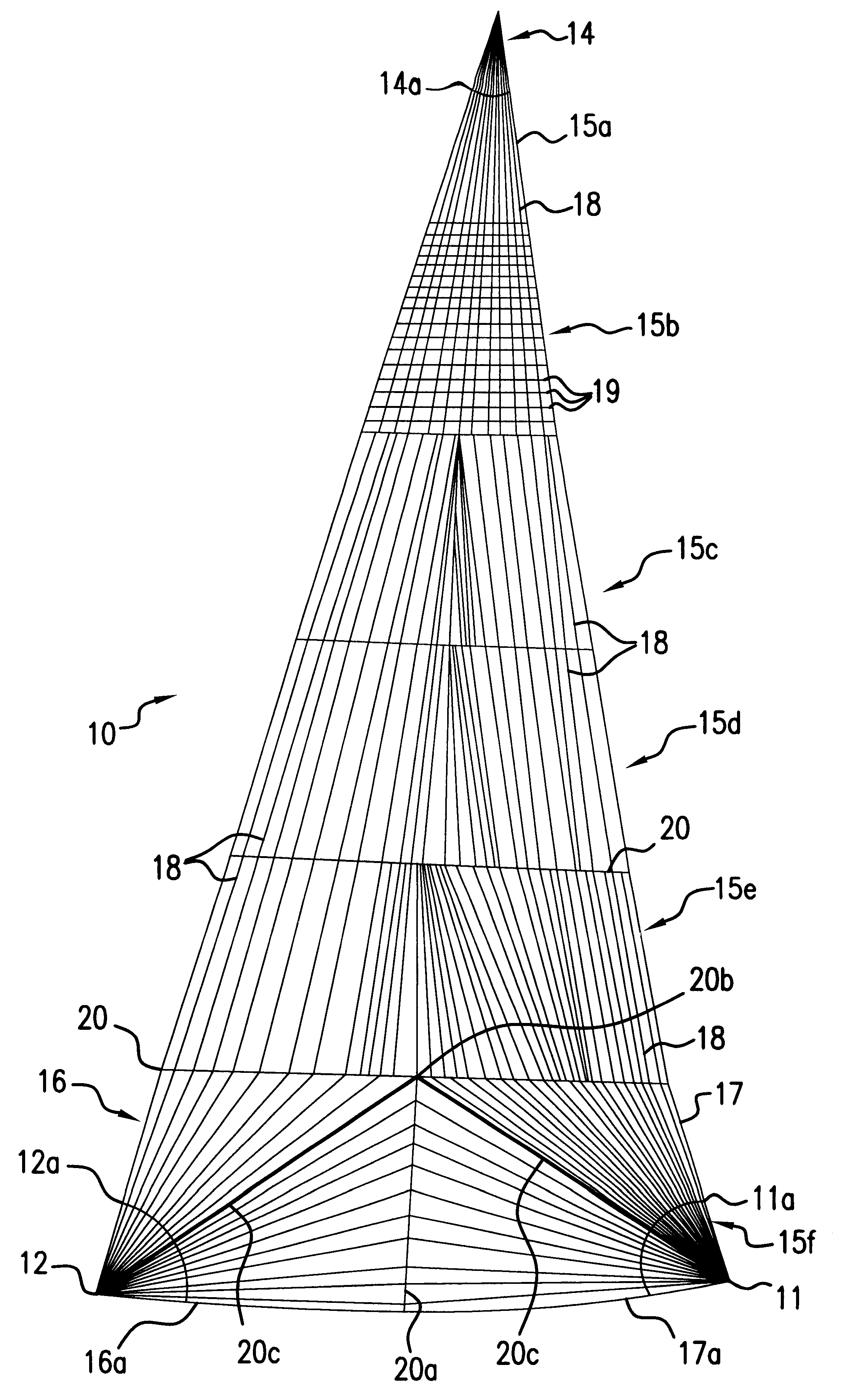
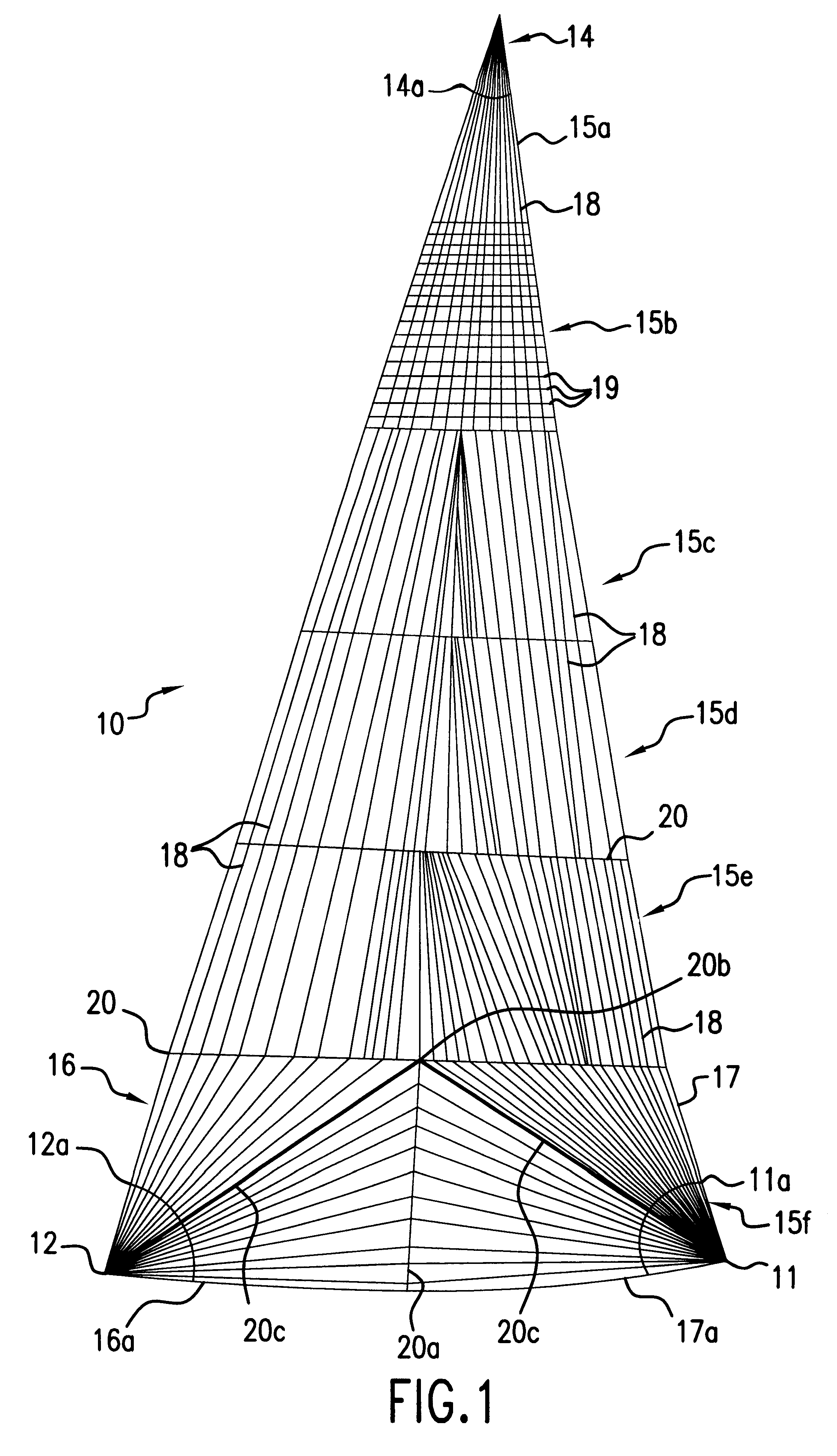
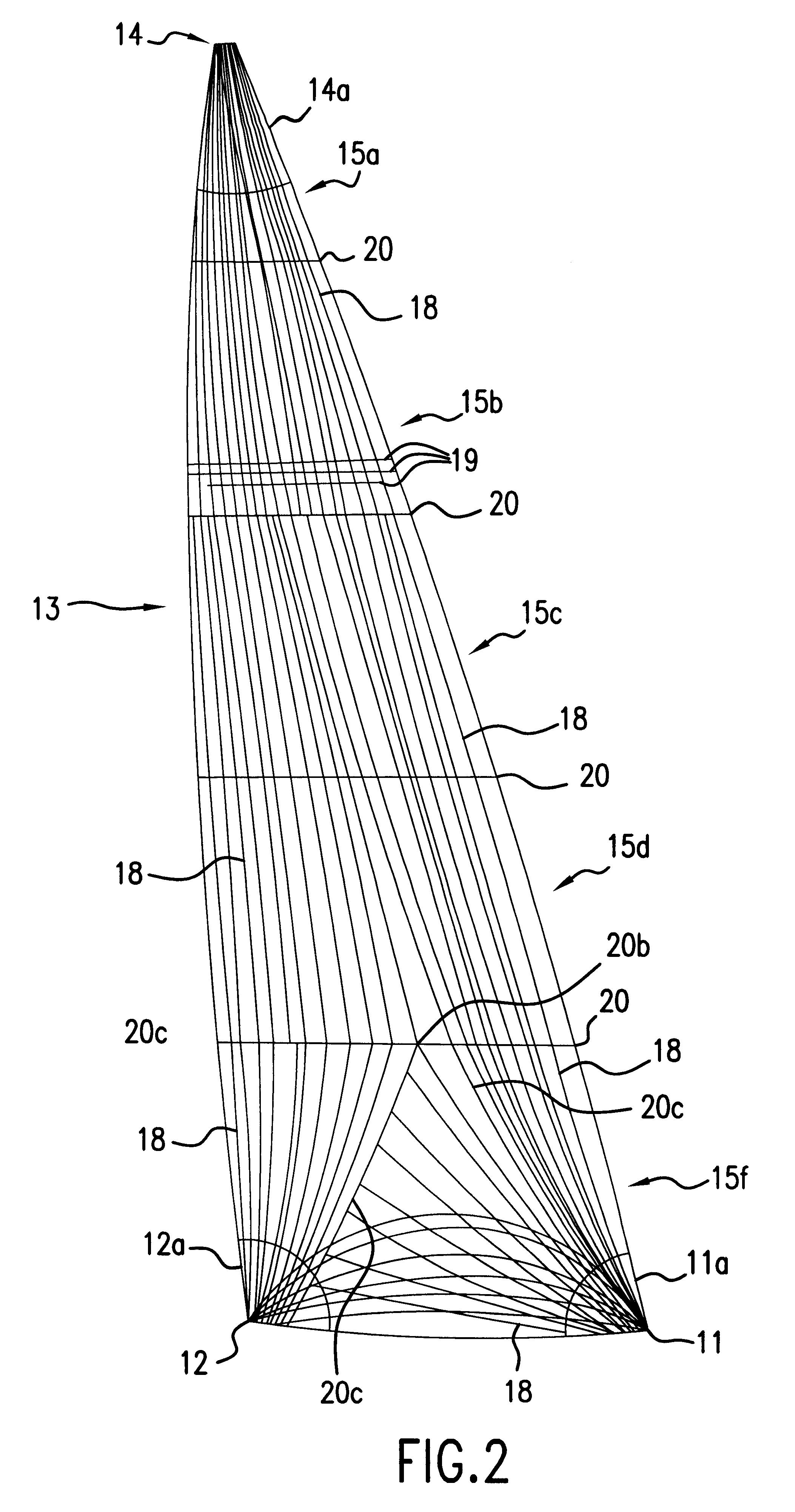
With reference to the drawings where like elements have been identified by the same numbers in the figures, FIG. 1 herein shows a typical genoa 10 also called a jib sail. Genoa sail 10 has a clew 11, tack 12, and a head 14. On the right side of the sail 10, between clew 11 and head 14 is an indefinite width area called a leach (not identified by a number). On the left-hand side of the sail 10, between tack 12 and head 14, is an indefinite width area called a luff (not identified by a number). Above and below an imaginary line between tack 12 and clew 11, is again an indefinite size area called the foot (not identified by a number). Typically, the luff and leach areas may be considered about one third the size of the panel in the horizontal direction.

In FIG. 1, the panels in the sails have been shown as 15a to 15f. Foot panel 15f consists of four sub panels 16, 16a, 17, and 17a respectively. These sub panels are indicated by the seam 20, the center seam 20a, the seam point 20b and th...


PUM

PropertyMeasurementUnit
Angleaaaaaaaaaa
Densityaaaaaaaaaa
Tenacityaaaaaaaaaa

Abstract

Fiber-oriented sails, including a method of manufacture, wherein woven, laminated panels of oriented fibers are of oriented fill yarns, e.g., in a woven cross-cut panel and the fill yarns, from panel to panel define load paths such as from head to clew and head to tack of a sail.

Description

This invention relates to fiber-oriented sails. More particularly, this invention relates to fiber-oriented sails in which the fill yarns in a single panel are oriented from panel to panel following the load paths. Accordingly, warp and fill woven panels follow fill defined catenary load paths in a particular panel for a particular sail.BACKGROUND FOR THE INVENTIONIn chronological order in the past century, sails have been made of woven textile materials. Base fibers for these textile materials were derived from natural polymers, i.e., cellulose, of which cotton and linen were preeminent. In general, the fibers in these textile yarns used for weaving sailcloth were of short length as it is typically found in natural polymers. However, significant advantage in sails was realized by longer length fibers and high quality sails were sold as being made of long length "Egyptian cotton" yarns.With the advent of synthetic fibers, that is an extruded bundle of "continuous" filaments for yarn...

Claims


Application Information

Patent Timeline
IPC IPC(8): B32B27/12B63H9/06B63H9/00D04H3/04D03D13/00D04H13/00D04H3/02
CPCB32B27/12B63H9/0657D03D13/00D04H3/04D04H13/002D03D13/002D03D13/008B63H2009/0678B63H9/0678B63H9/067
Inventor KEIRE, FRED AIVARS
Owner KEIRE FRED AIVARS
Why Eureka
Try Eureka