
Device for generating a pulsatile fluid drug flow

Inactive Publication Date: 2001-11-06
ELAN PHRMA INT LTD
View PDF3 Cites 133 Cited by
  • Summary
  • Abstract
  • Description
  • Claims
  • Application Information

AI Technical Summary

Benefits of technology

Thus, the invention provides a device for generating a pulsatile fluid drug flow, comprising a housing containing an expandable-contractible chamber having an inlet and an outlet, a valve associated with the outlet which is actuated by the expansion and contraction of the chamber, and means for biasing the chamber to its contracted state, such that when the inlet is connected to a pressurised fluid drug supply the chamber is expanded by the drug, the expansion of the chamber actuating the valve to open, thereby allowing release of the drug from the chamber and enabling the contraction of the chamber under the influence of the biasing means, this contraction in turn actuating the valve to close thereby allowing the chamber to refill.
The device according to the invention automatically generates pulses of a drug from any pressurised supply. It converts any pressurised supply into a pulsatile flow without the need for any power source and can therefore be designed as an extremely simple unpowered mechanical device. It will be appreciated that the device according to the invention can be coupled to a standard continuous drug pump and can therefore provide a simple, cheap and effective pulsatile drug source which has none of the complexity of existing variable rate powered drug pumps.
This provides the most efficient pumping for a given chamber volume as the chamber refills and empties substantially completely during each pumping cycle.
In one embodiment, the outlet is formed by an aperture in the displaceable member, said aperture forming a seat for the valve, and the valve comprises a blocking member which is adapted to move into and out of sealing engagement with the seat, thereby opening and closing said outlet. This arrangement positively links the opening and closing of the valve with the movement of the displaceable member, further ensuring that the chamber empties and refills correctly.
The shape of the valve component and the actuating member thus allow for the hysteresis effect referred to above, as the actuating member is able to begin changing configurations without influencing the valve; the valve is only actuated when the actuating member has fully changed configurations, i.e. it has moved from a position where it was engaging one of said sections of greater thickness to a position where it engages the other section of greater thickness, and the intermediate section allows the actuating member to make this transition before the valve is actuated.
Thus, the device can be connected to a simple, cheap pump in order to adapt the pump for pulsatile delivery.

Problems solved by technology

Pumps for delivering drugs to a human or animal subject range from simple cheap devices to expensive, complicated microchip-controlled devices.
Again, cheap devices having a reliable delivery rate are available using such technologies, although even in devices employing an electrolytic cell the expense and complexity is increased by the necessity of including a battery.
The primary limitation with such devices, some of which have been available since the 1970s, is that they are only suitable in situations where a steady, continuous flow of drug is desired.
While other devices have certainly been disclosed which can be used to effect pulsatile drug delivery, such devices in no way approach the simplicity or cheapness of the basic single rate devices referred to above.
These devices employ mechanisms which are in many cases less reliable than single rate devices, and they are generally significantly more expensive to produce.

Method used


Image

  • Device for generating a pulsatile fluid drug flow
  • Device for generating a pulsatile fluid drug flow
  • Device for generating a pulsatile fluid drug flow

Examples


Embodiment Construction

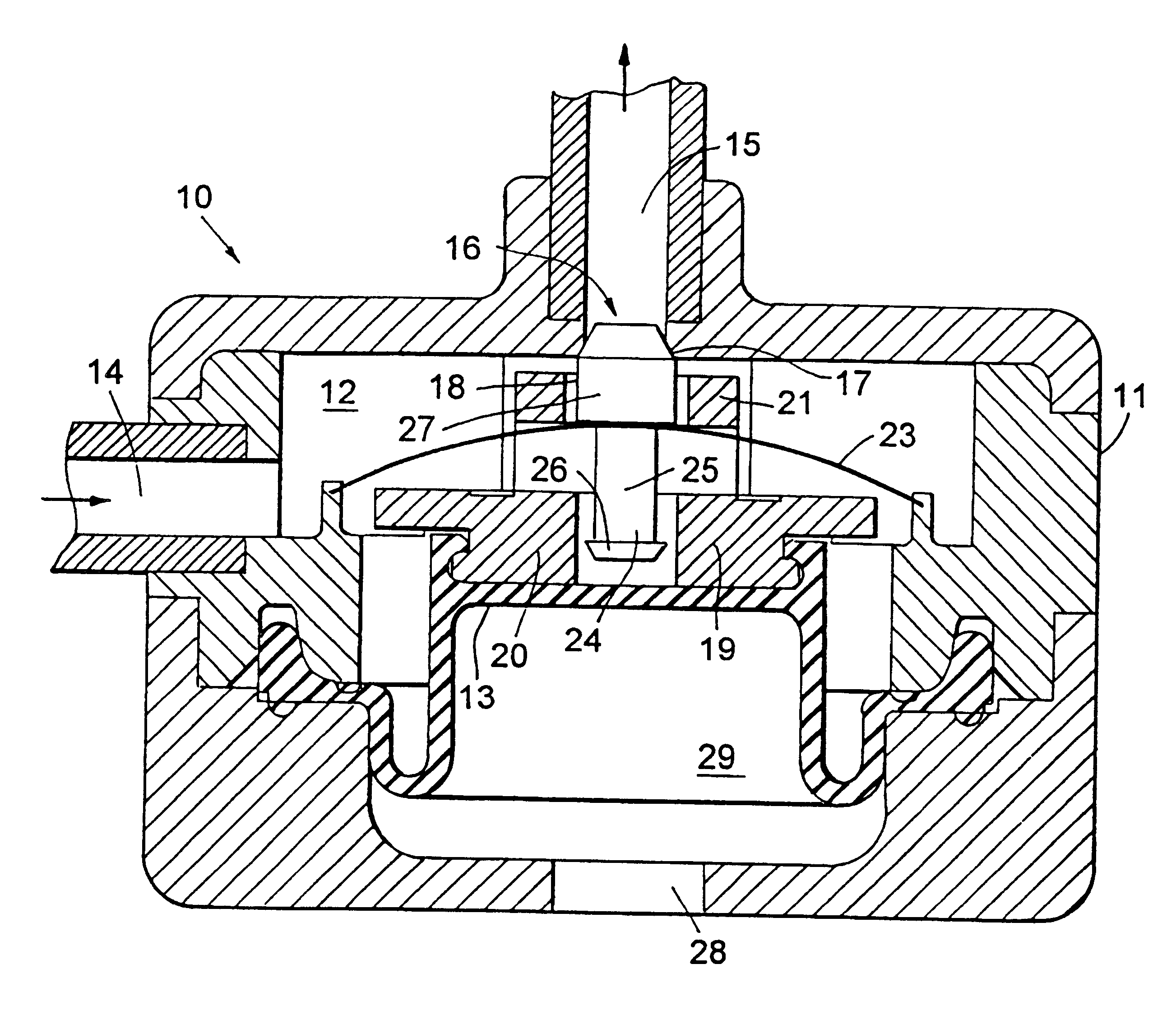
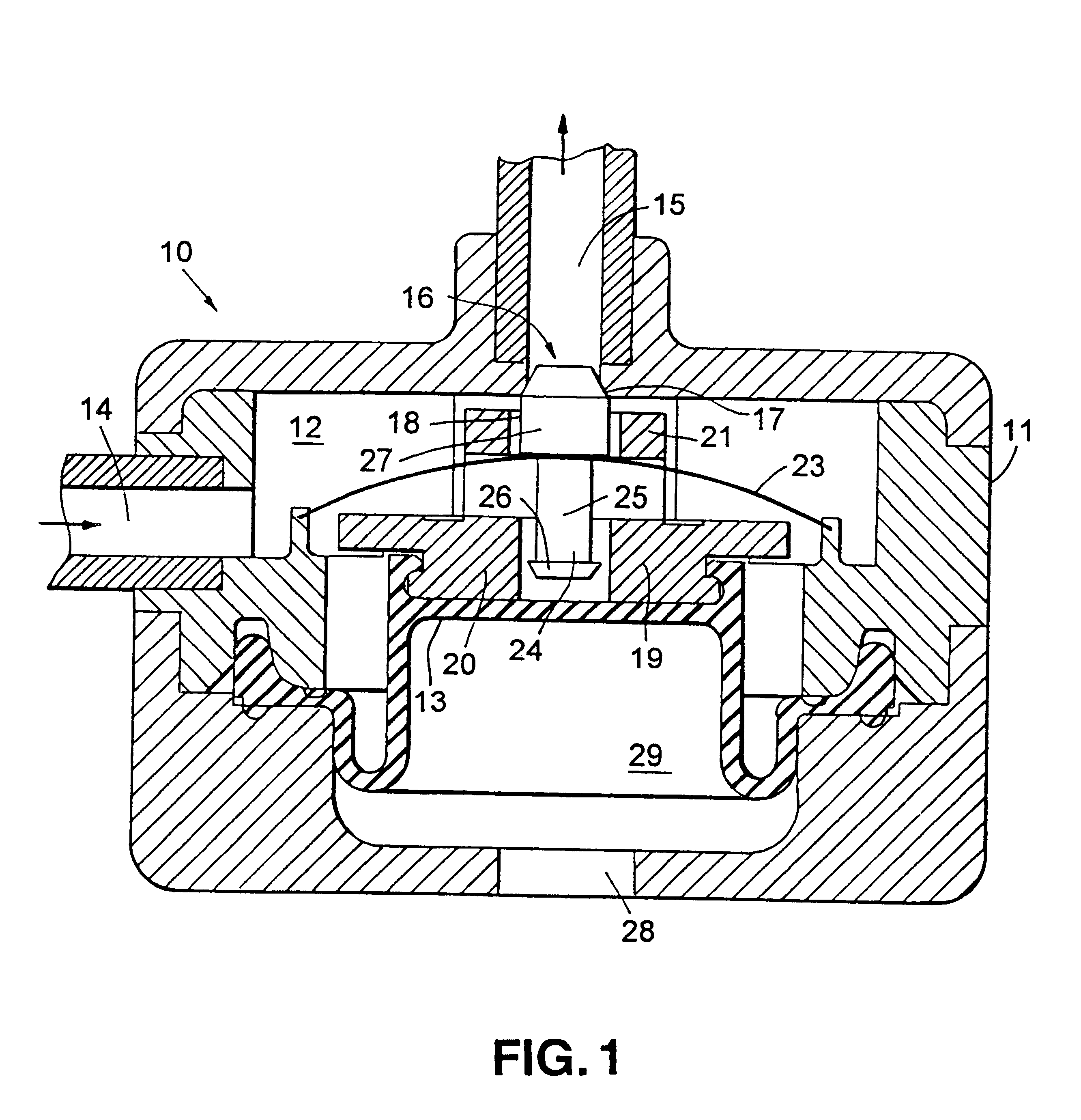
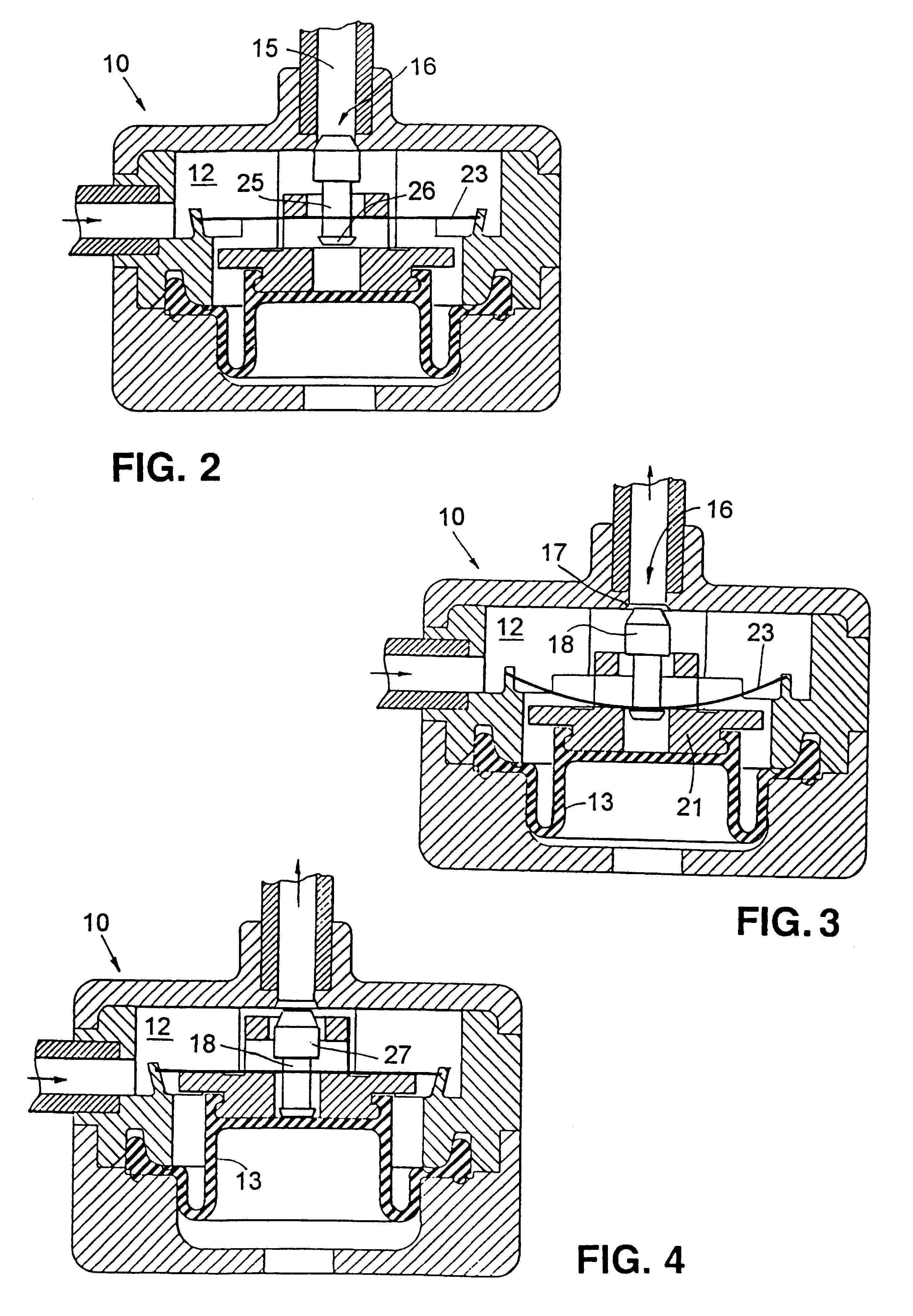
In FIG. 1 there is indicated, generally at 10, a device according to the invention comprising a generally cylindrical housing 11, seen here in sectional elevation, which contains an internal chamber 12 defined in part by a diaphragm 13. Diaphragm 13 is able to move downwards and upwards so as to expand and contract chamber 12. Chamber 12 is provided with an inlet 14 which can be connected to a continuous drug pump and an outlet 15 through which drug can be pumped from the chamber 12. A valve 16, in the form of a valve seat 17 and a blocking member 18, controls the flow of drug from chamber 12 through outlet 15.

Diaphragm 13 is provide with support member 19 which comprises a lower annular section 20 and an upper annular section 21. An actuating member in the form of a spring 23 is mounted within housing 11 such that it is situated between the upper and lower annular sections 20,21. Spring 23 consists of a thin convex circular metal disc which can be flipped to a concave configuration...


PUM


Abstract

A device (10) for generating a pulsatile fluid drug flow comprises a housing (11) containing an expandable-contractible chamber (12) having an inlet (14) and an outlet (15), a valve (16) associated with the outlet (15) which is actuated by the expansion and contraction of the chamber (12), and means (13, 23) for biasing the chamber (12) to its contracted state. When the inlet (14) is connected to a pressurised fluid drug supply the chamber (12) is expanded by the drug, and this expansion of the chamber (12) actuates the valve (16) to open, thereby allowing release of the drug from the chamber (12), following which the chamber (12) contracts under the influence of the biasing means (13, 23), this contraction in turn actuating the valve (16) to close thereby allowing the chamber (12) to refill. By this mechanism, a constant supply of liquid, such as from an osmotic or elastomeric drug delivery pump, can be converted to a pulsatile flow, which may provide a more suitable delivery of certain drugs.

Description

This invention relates to drug delivery devices and in particular to pulsatile drug delivery devices.Pumps for delivering drugs to a human or animal subject range from simple cheap devices to expensive, complicated microchip-controlled devices. Amongst the cheapest and least complicated devices are osmotic and elastomeric pumps.Osmotic pumps such as the "ALZET" (Trade Mark) pump produced by the Alza Corporation, Calif., rely on osmotic pressure developed between an aqueous environment and an osmotic solution to drive a drug from a reservoir. Elastomeric pumps such as the "INFUSOR" (Trade Mark) pump produced by Baxter Healthcare Corporation, Ill., rely on the contraction of an expanded elastomeric reservoir to drive the drug from the reservoir. Both types of pump are advantageous primarily as a result of their simplicity, cheapness and reliability. Developments in technology have led to a situation where a highly reliable rate of drug delivery can be obtained from such devices.Simila...

Claims


Application Information

Patent Timeline
IPC IPC(8): A61M39/00A61M5/145A61M39/22A61M5/142
CPCA61M5/14593A61M39/22A61M5/142A61M2206/10
Inventor GROSS, JOSEPH
Owner ELAN PHRMA INT LTD
Features
  • Generate Ideas
  • Intellectual Property
  • Life Sciences
  • Materials
  • Tech Scout
  • Unparalleled Data Quality
  • Higher Quality Content
  • 60% Fewer Hallucinations
Learn More