Al technical title is built by PatSnap Al team. It summarizes the technical point description of the patent document.
an in vivo monitoring and analyte technology, applied in the field of in vivo monitoring devices of analyte, can solve the problems of inability to monitor the level of glucose or other analytes continuously or automatically, affecting the effect of high or low glucose or other analytes, and affecting the quality of life of patients, etc., and achieve the effect of improving the quality of life and reducing the risk of diabetes
Inactive Publication Date: 2005-09-15
ABBOTT DIABETES CARE INC
View PDF100 Cites 599 Cited by
Summary
Abstract
Description
Claims
Application Information
AI Technical Summary
This helps you quickly interpret patents by identifying the three key elements:
Problems solved by technology
Method used
Benefits of technology
Problems solved by technology
High or low levels of glucose or other analytes may be have detrimental effects.
This technique does not permit continuous or automatic monitoring of glucose levels in the body, but typically must be performed manually on a periodic basis.
Unfortunately, the consistency with which the level of glucose is checked varies widely among individuals.
Many diabetics find the periodic testing inconvenient and they sometimes forget to test their glucose level or do not have time for a proper test.
These situations may result in hyperglycemic or hypoglycemic episodes.
However, these devices are often difficult to reproducibly and inexpensively manufacture in large numbers.
In addition, these devices are typically large, bulky, and / or inflexible, and many can not be used effectively outside of a controlled medical facility, such as a hospital or a doctor's office, unless the patient is restricted in his activities.
These sensor guides are typically bulky and do not allow for freedom of movement.
The size of the sensor guides and presence of cables and wires hinders the convenient use of these devices for everyday applications.
Method used
Image
Click on the blue label to locate the original text in one second.
Reading with bidirectional positioning of images and text.
Examples
Embodiment Construction
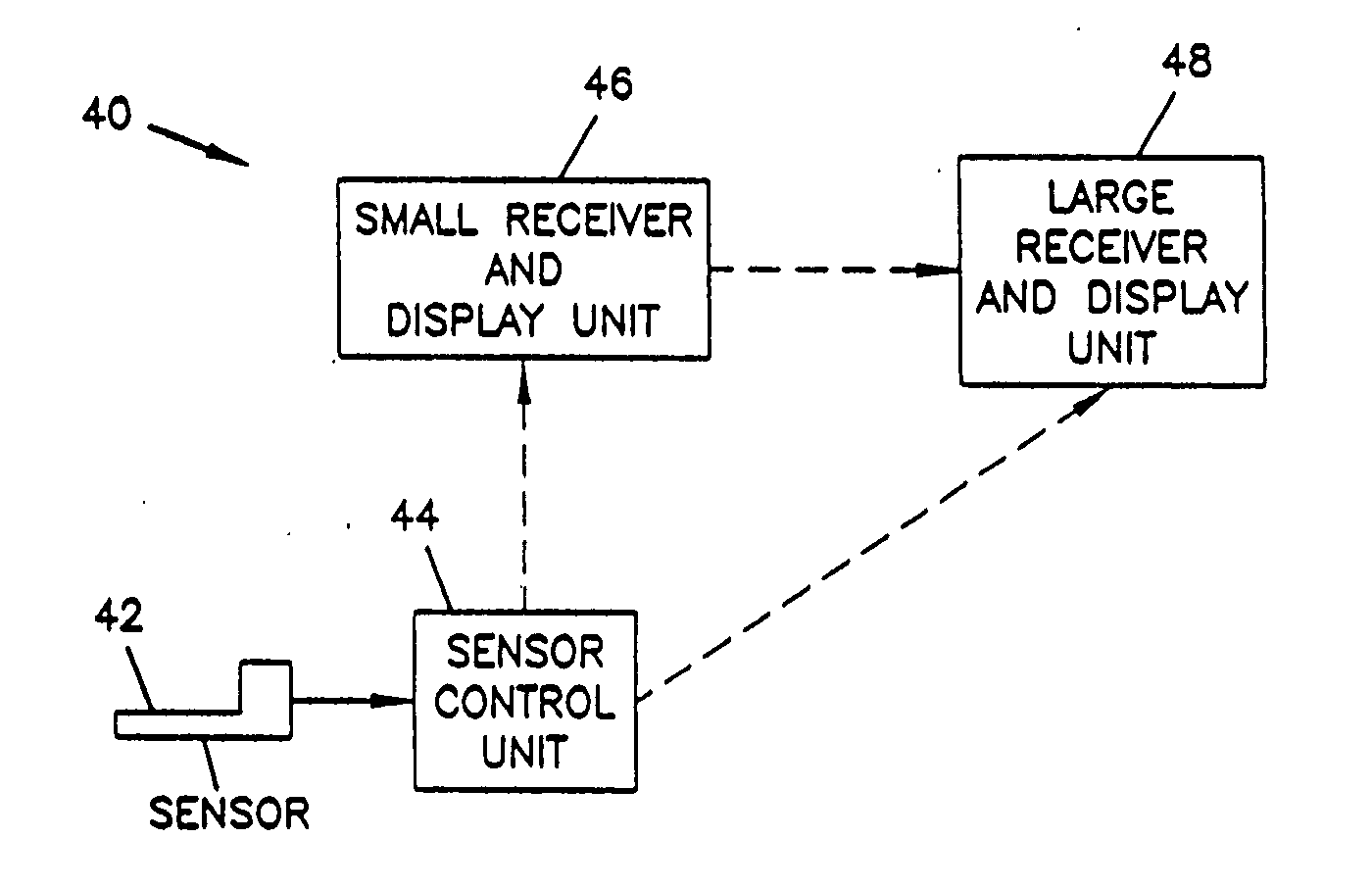
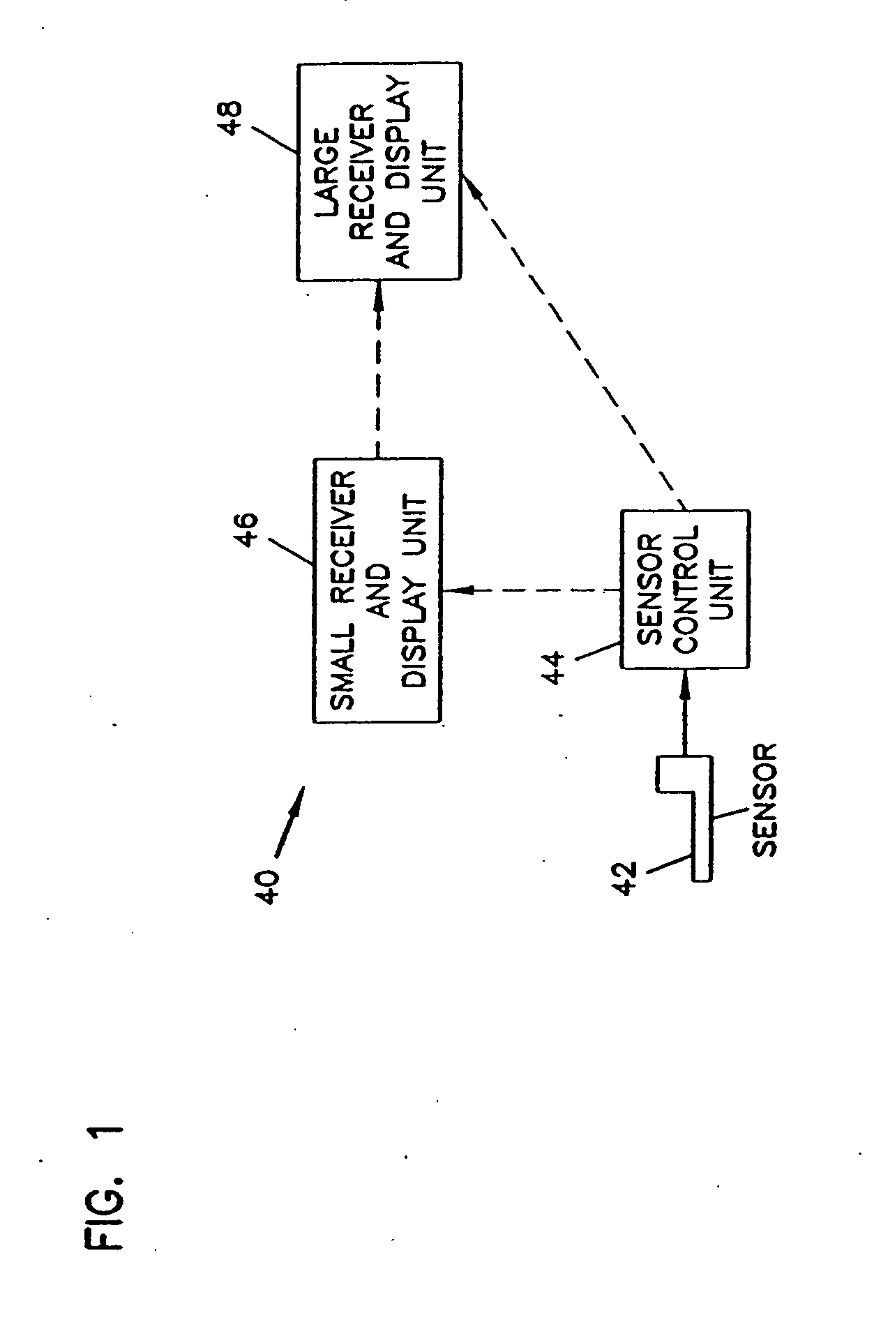
[0056] The present invention is applicable to an analyte monitoring system using an implantable sensor for the in vivo determination of a concentration of an analyte, such as glucose or lactate, in a fluid. The sensor can be, for example, subcutaneously implanted in a patient for the continuous or periodic monitoring an analyte in a patient's interstitial fluid. This can then be used to infer the glucose level in the patient's bloodstream. Other in vivo analyte sensors can be made, according to the invention, for insertion into a vein, artery, or other portion of the body containing fluid. The analyte monitoring system is typically configured for monitoring the level of the analyte over a time period which may range from days to weeks or longer.
[0057] The following definitions are provided for terms used herein:
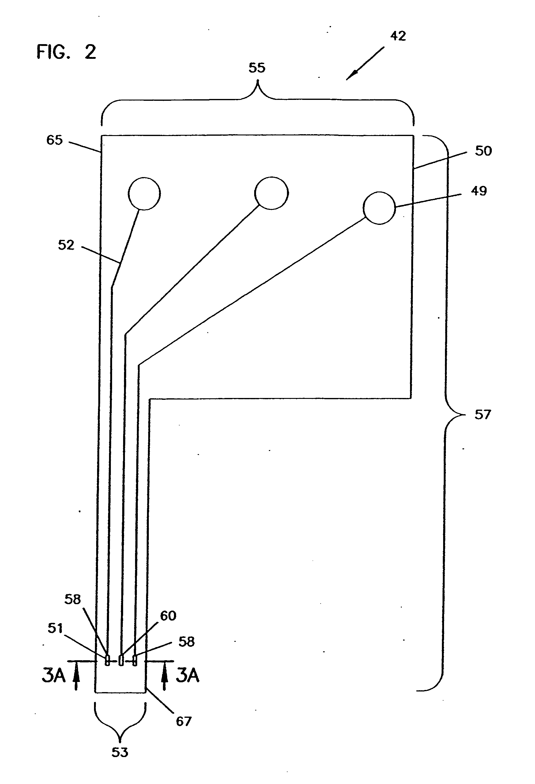
[0058] A “counter electrode” refers to an electrode paired with the working electrode, through which passes a current equal in magnitude and opposite in sign to the current...
PUM
Property
Measurement
Unit
time period
aaaaa
aaaaa
time period
aaaaa
aaaaa
time period
aaaaa
aaaaa
Abstract
An analyte monitor includes a sensor, a sensor control unit, and a display unit. The sensor has, for example, a substrate, a recessed channel formed in the substrate, and conductive material disposed in the recessed channel to form a working electrode. The sensor control unit typically has a housing adapted for placement on skin and is adapted to receive a portion of an electrochemical sensor. The sensor control unit also includes two or more conductive contacts disposed on the housing and configured for coupling to two or more contact pads on the sensor. A transmitter is disposed in the housing and coupled to the plurality of conductive contacts for transmitting data obtained using the sensor. The display unit has a receiver for receiving data transmitted by the transmitter of the sensor control unit and a display coupled to the receiver for displaying an indication of a level of an analyte. The analyte monitor may also be part of a drug delivery system to alter the level of the analyte based on the data obtained using the sensor.
Description
RELATED APPLICATIONS [0001] This application is a continuation of pending application Ser. No. 10 / 420,057 filed Apr. 18, 2003 which is a continuation of application Ser. No. 09 / 667,199 filed Sep. 21, 2000, now U.S. Pat. No. 6,565,509 B1, which is a continuation of application Ser. No. 09 / 070,677 filed Apr. 30, 1998 now U.S. Pat. No. 6,175,752 B1, the disclosure of each of which are incorporated herein by reference for all purposes, and each of which are assigned to assignee, TheraSense, Inc., of Alameda, Calif.FIELD OF THE INVENTION [0002] The present invention is, in general, directed to devices and methods for the in vivo monitoring of an analyte, such as glucose or lactate. More particularly, the present invention relates to devices and methods for the in vivo monitoring of an analyte using an electrochemical sensor to provide information to a patient about the level of the analyte. BACKGROUND OF THE INVENTION [0003] The monitoring of the level of glucose of other analytes, such ...
Claims
Application Information
Patent Timeline
Application Date:The date an application was filed.
Publication Date:The date a patent or application was officially published.
First Publication Date:The earliest publication date of a patent with the same application number.
Issue Date:Publication date of the patent grant document.
PCT Entry Date:The Entry date of PCT National Phase.
Estimated Expiry Date:The statutory expiry date of a patent right according to the Patent Law, and it is the longest term of protection that the patent right can achieve without the termination of the patent right due to other reasons(Term extension factor has been taken into account ).
Invalid Date:Actual expiry date is based on effective date or publication date of legal transaction data of invalid patent.
Patent Type & Authority Applications(United States)
Inventor SAY, JAMESTOMASCO, MICHAEL F.HELLER, ADAMGAL, YORAMARIA, BEHRADHELLER, EPHRAIMPLANTE, PHILLIP JOHNVREEKE, MARK S.FRIEDMAN, KEITH A.COLMAN, FREDRIC C.