Plug neck for a filler neck of a fuel tank

Inactive Publication Date: 2001-11-20
MANNESMANN VDO AG
View PDF5 Cites 15 Cited by
  • Summary
  • Abstract
  • Description
  • Claims
  • Application Information

AI Technical Summary

Problems solved by technology

This results, in particular in the case of mass production, in very cost-intensive production of the plug neck.
This would require at least four connections an

Method used


Image

  • Plug neck for a filler neck of a fuel tank
  • Plug neck for a filler neck of a fuel tank
  • Plug neck for a filler neck of a fuel tank

Examples


Embodiment Construction

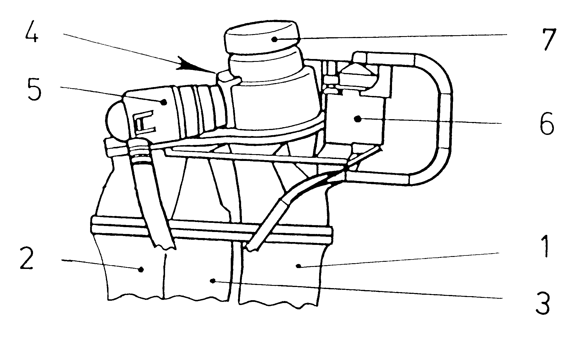
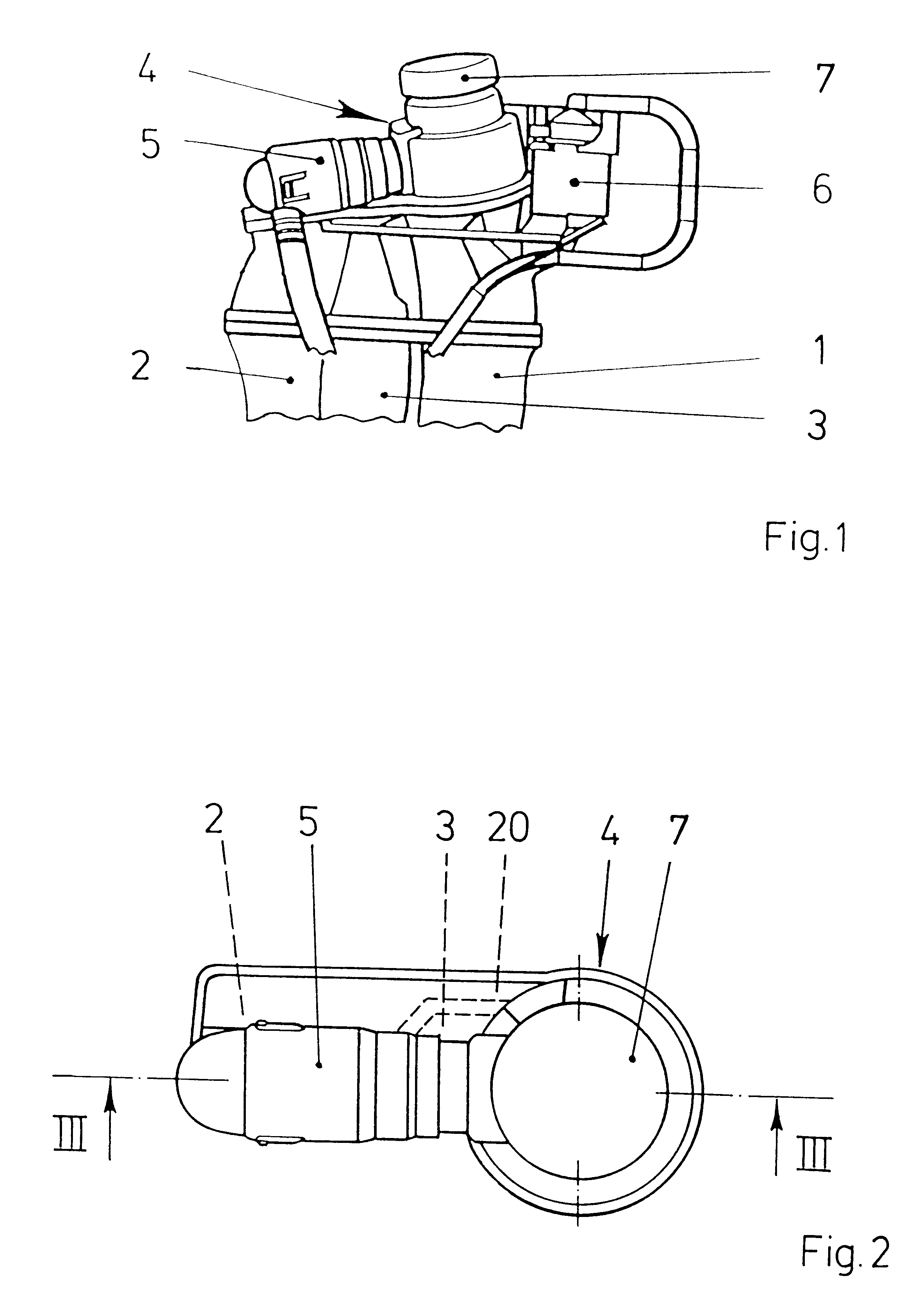
FIG. 1 shows a filler neck 1 for a fuel tank of a motor vehicle with two compensation chambers 2, 3 and a plug neck 4. The plug neck 4 has a vent valve 5 which is connected to the two compensation chambers 2, 3. Furthermore, a roll-over valve 6 is connected to the plug neck 4. The vent valve 5 and the roll-over valve 6 are each connected to an activated carbon filter (not illustrated). On the top side, the plug neck 4 has a closure cover 7.

FIG. 2 illustrates the plug neck 4 from FIG. 1 in an enlarged view from above. It can be seen here that a first compensation chamber 2 has a channel 20 routed to the plug neck 4, while the second compensation chamber 3 adjoins the plug neck 4 directly.

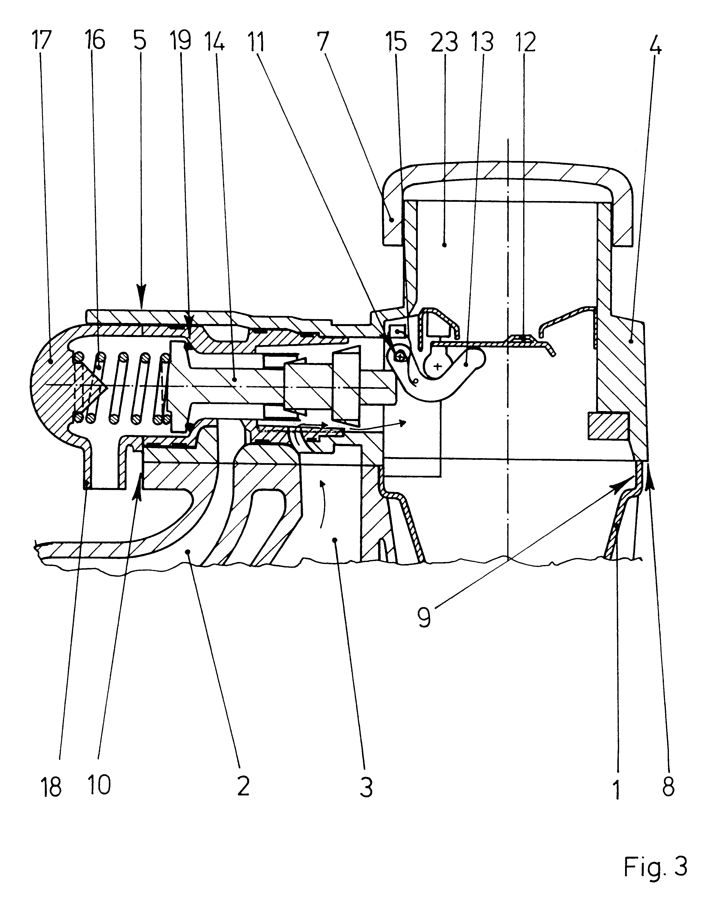
FIG. 3 shows the plug neck 4 from FIG. 2 in a sectional illustration along line III--III. The plug neck 4 and the filler neck 1 have a common central refueling channel 23. The plug neck 4 has a flange 8 for abutment against flanges 9, 10 of the compensation tanks 2, 3 and of the filler neck 1. Arrang...


PUM


Abstract

A plug neck for a filler neck of a motor vehicle has exchanging means for refueling-venting adaptation to different refueling devices. In the case of a refueling device which removes gases from a refueling channel by suction, a compensation chamber is connected permanently to the refueling channel via a connecting channel. For adaptation to a refueling device without suction removal, the connecting channel is closed and the vent valve is provided with a cap which has a connection neck for a line leading to an activated carbon filter. This allows tool costs for producing the plug neck to be kept particularly low.

Description

The invention relates to automotive fuel tanks and specifically to a plug neck for a filler neck of a fuel tank of a motor vehicle having a flap which is arranged in a refueling channel which can be moved during refueling and is intended for switching a vent valve.DESCRIPTION OF THE RELATED ARTFuel tank plug necks are known for preventing the escape of fuel vapors during refueling and for pressure equalization with the surroundings during operation. At the end which is directed away from the filler neck, the plug neck bears a fuel-tank closure cover. In the operating position, the second compensation chamber, for the overflow of air in the vent valve, is connected to the refueling channel. During refueling, the flap is opened via a rocker lever and adjusts the vent valve into a position in which it closes the second compensation chamber. During refueling, air located in the fuel tank is discharged via the first compensation chamber.It is necessary for the plug neck to be adapted for...

Claims


Application Information

Patent Timeline
IPC IPC(8): B60K15/04B60K15/035B60K15/03
CPCB60K15/035B60K15/03519B60K15/04B60K2015/03571B60K2015/03576
Inventor ZAPP, THOMASREITER, FRANK
Owner MANNESMANN VDO AG
Why Eureka
Try Eureka