

Liquid jet printing head and liquid jet printing apparatus provided with said liquid jet printing head
a liquid jet printing and printing head technology, applied in printing and other directions, can solve the problems of reducing affecting the discharge direction of ink droplets, and affecting the discharge speed of ink droplets
- Summary
- Abstract
- Description
- Claims
- Application Information
AI Technical Summary
Benefits of technology
Problems solved by technology
Method used
Image

Examples
first head embodiment
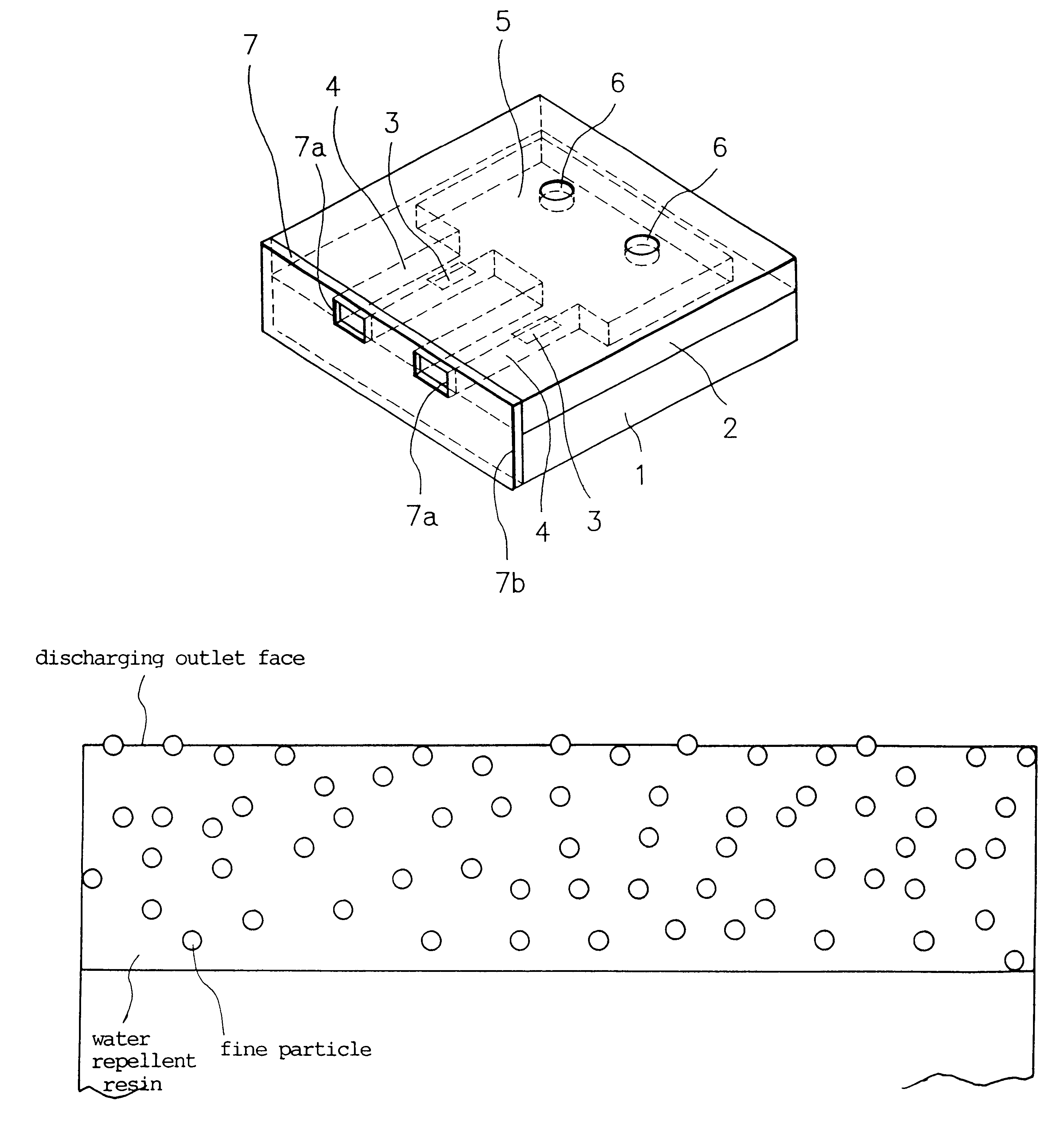
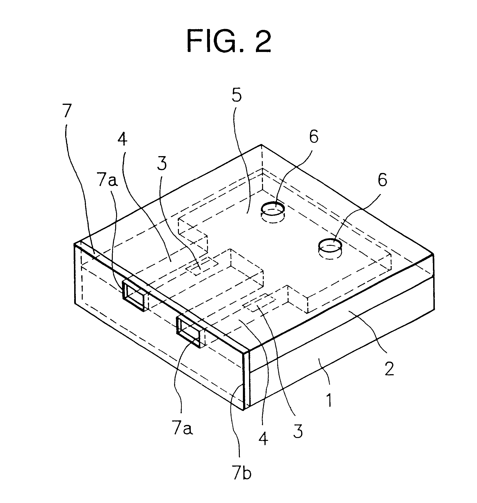
A liquid jet printing head including a discharging outlet for discharging liquid; a substrate for a liquid jet printing head including an electrothermal converting body comprising a heat generating resistor capable of generating a thermal energy for discharging liquid from the discharging outlet and a pair of wirings electrically connected to the heat generating resistor, the pair of wirings being capable of supplying an electric signal for generating the thermal energy to the heat generating resistor; and a liquid supplying pathway disposed in the vicinity of the electrothermal converting body of the substrate, wherein the discharging outlet is disposed at a discharging outlet face, characterized in that the discharging outlet face is provided with a water repellent material layer comprised of a water repellent resin composition comprising a water repellent resin containing inorganic fine particles distributed therein in a desired distribution state.
The liquid jet printing head acc...
second head embodiment
A liquid jet printing head including a discharging outlet for discharging liquid; a substrate for a liquid jet printing head including an electrothermal converting body comprising a heat generating resistor capable of generating thermal energy for discharging liquid from the discharging outlet and a pair of wirings electrically connected to the heat generating resistor, the pair of wirings being capable of supplying an electric signal for generating the thermal energy to the heat generating resistor; and a liquid supplying pathway disposed in the vicinity of the electrothermal converting body of the substrate, wherein the discharging outlet is disposed at a discharging outlet face, characterized in that the discharging outlet face is provided with a water repellent material layer comprised of a water repellent resin composition comprising a water repellent resin containing inorganic fine particles distributed therein in a desired distribution state and wherein some of the inorganic ...
first apparatus embodiment
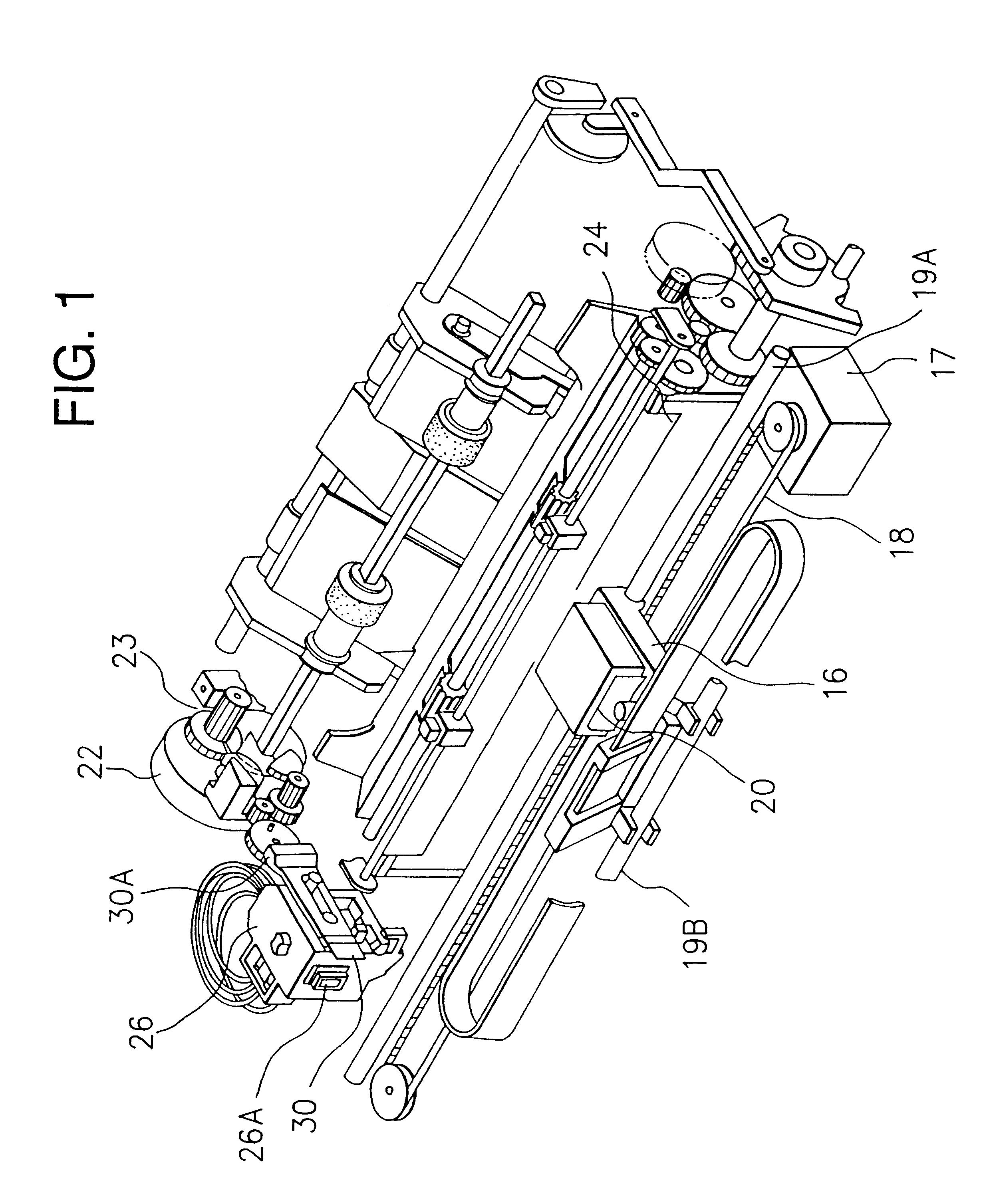
A liquid jet printing apparatus comprising: (a) a liquid jet printing head including a discharging outlet for discharging liquid, a substrate for a liquid jet printing head including an electrothermal converting body comprising a heat generating resistor capable of generating a thermal energy for discharging liquid from the discharging outlet and a pair of wirings electrically connected to the heat generating resistor, the pair of wirings being capable of supplying an electric signal for generating the thermal energy to the heat generating resistor, and a liquid supplying pathway disposed in the vicinity of the electrothermal converting body of the substrate, wherein the discharging outlet is disposed at a discharging outlet face; and (b) an electric signal supplying means capable of supplying an electric signal to the heat generating resistor of the printing head, characterized in that the discharging outlet face of the printing head is provided with a water repellent material laye...
PUM
 Abstract
Description
Claims
Application Information