Solar generator with electrically conducting hinges

Inactive Publication Date: 2001-11-20
DAIMLER AG
View PDF9 Cites 42 Cited by
  • Summary
  • Abstract
  • Description
  • Claims
  • Application Information

AI Technical Summary

Benefits of technology

The hinged electrical and mechanical interconnection according to the invention can function without damage over the entire life of a flexible solar generator exposed to 36000 thermal cycles of +100.degree. C. to -100.degree. C. in low earth orbit or 2000 thermal cycles of +100.degree. C. to -180.degree. C. in geostationary orbit. The present panels can be folded and unfolded or rolled and unrolled repeatedly for any purpose such as testing, system integration, stowing on earth and unfolding or unrolling in o

Problems solved by technology

These flexible conductors or bridging elements can cause the solar generators to fail due to thermal and mechanical stress.
Further, such

Method used


Image

  • Solar generator with electrically conducting hinges
  • Solar generator with electrically conducting hinges
  • Solar generator with electrically conducting hinges

Examples


Embodiment Construction

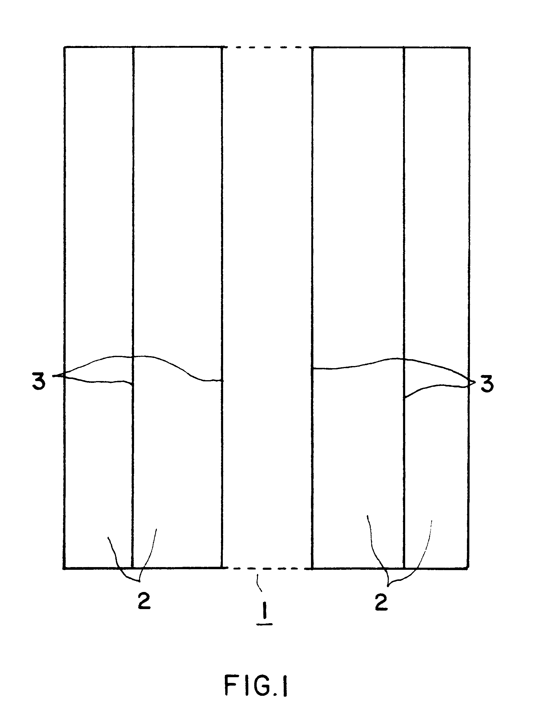
The array 1 in FIG. 1 of a flexible solar generator comprises several blankets or panels 2 that are connected in a foldable manner by electrically conducting piano hinges 3. In FIG. 1, the dotted line indicates that an array 1 normally comprises more than four blankets or panels 2 that are schematically shown in FIG. 1.

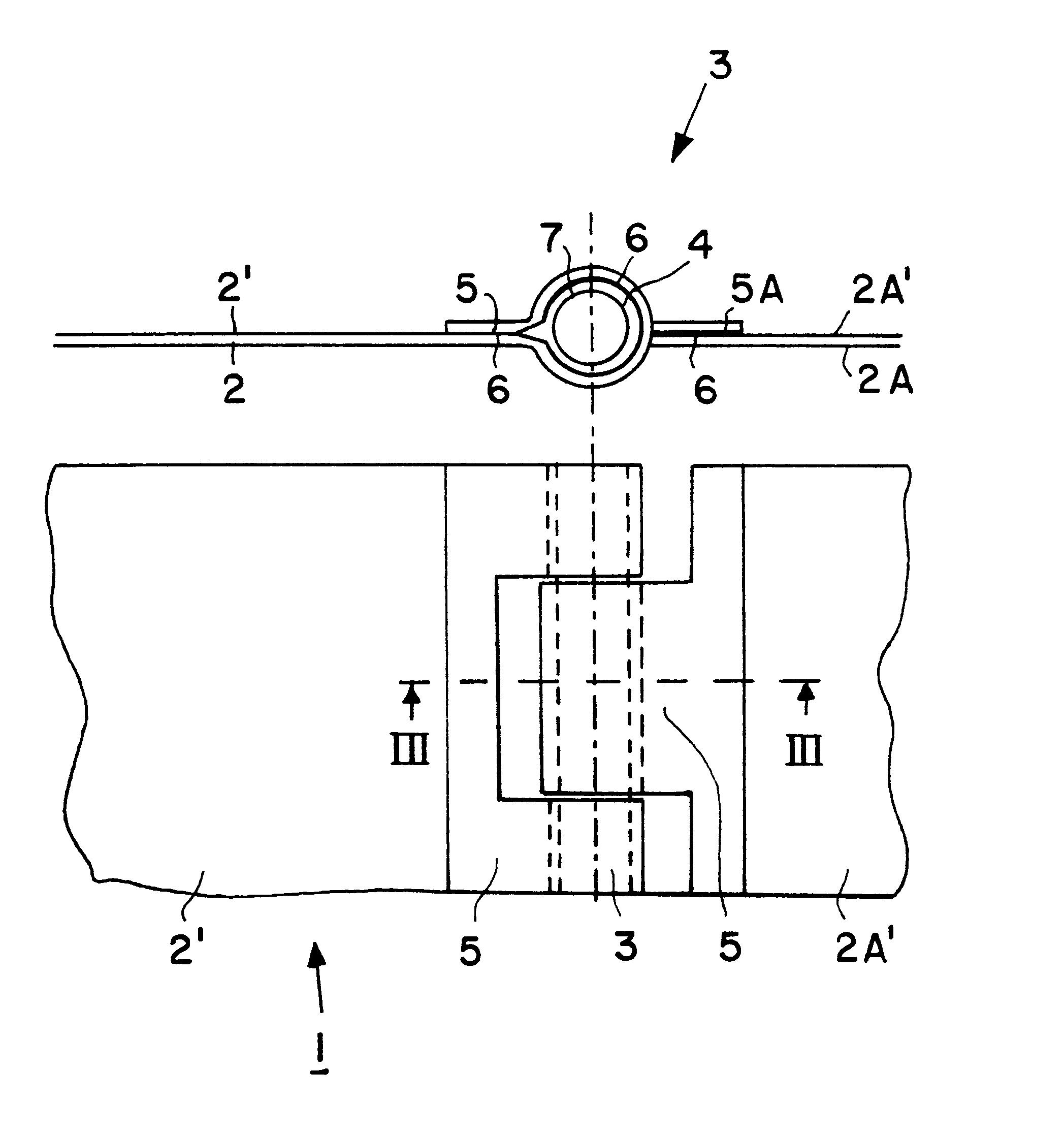
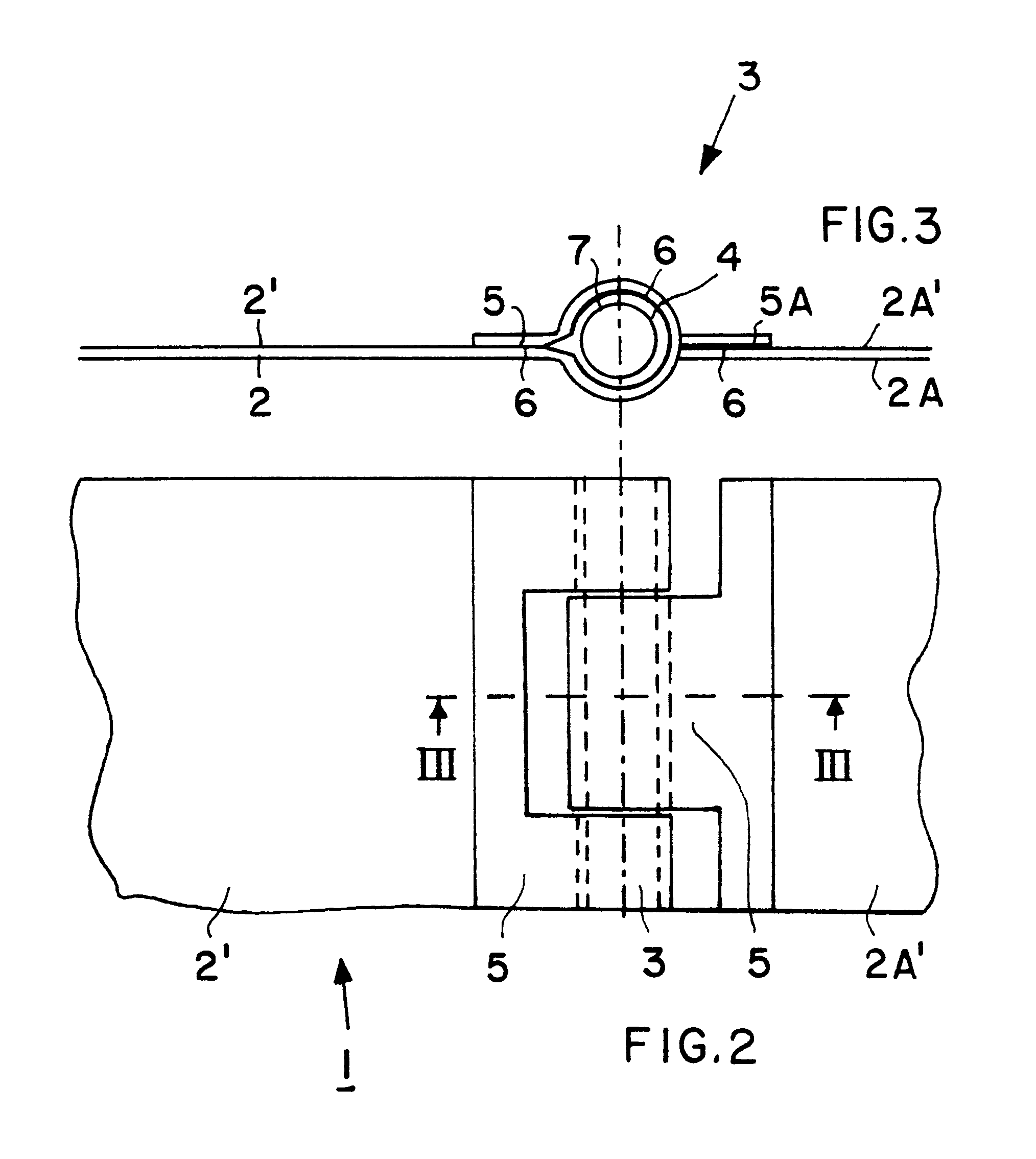
FIGS. 2 and 3 show a plan view of a hinge portion and a section of the electrical hinged interconnection of the conductive back-sides of neighboring panels 2 and 2A in the array 1. Each panel 2, 2A has an electrically conducting backside surface 2', 2A'. The electrical interconnection according to the invention is provided directly by the hinges 3 that are made of electrically conductive material. Electrically conducting tubular hinge elements 4 of the hinges 3 are fixed by an electrically conductive adhesive 6 to neighboring edges of the electrically conductive backsides 2', 2A' of the panels 2, whereby an electrical connection is formed between the conductive backsi...


PUM


Abstract

The electrically conducting backsides of solar blankets forming arrays are electrically interconnected by electrically conducting hinges. Tubular hinge elements are connected in an electrically conducting manner to edges of the blankets and an electrically conducting hinge pin extends through the tubular hinge elements.

Description

The invention relates to solar panels interconnected by hinges to form a flexible solar generatorBACKGROUND INFORMATIONThe backsides of flexible solar generators must be electrically conductive for certain uses to dissipate electrostatic charges. Support films, so-called blankets or panels carrying solar cells, are coated on their backside with conductive material or with electrically conductive support films, such as black kapton (Trademark), are used as carrier panels or blankets. In an array of a flexible solar generator comprising several panels or blankets interconnected by hinges, the electrically-conductive surfaces of the blanket or panel must be electrically interconnected for dissipating static charges. Conventionally flexible conductors are bridging the hinge joints. These flexible conductors or bridging elements can cause the solar generators to fail due to thermal and mechanical stress. Further, such bridging elements add to the costs of the panels due to quality requir...

Claims


Application Information

Patent Timeline
IPC IPC(8): H01L31/05H01L31/043H02S30/20
CPCH02S30/20H01L31/0508H01L31/043F24J2002/5486Y02E10/50F24S2030/16
Inventor KUECHLER, GUNTER
Owner DAIMLER AG
Why Eureka
Try Eureka