Energy absorber

a technology of energy absorber and absorber, which is applied in the direction of vibration dampers, protective foundations, building components, etc., can solve the problem of taking a considerable amount of time for the structure to come to rest, and achieve the effect of high coefficient of friction

Inactive Publication Date: 2001-11-27
ROBINSON SEISMIC
View PDF14 Cites 68 Cited by
  • Summary
  • Abstract
  • Description
  • Claims
  • Application Information

AI Technical Summary

Benefits of technology

More preferably said rubber outer layer is reinforced rubber.
Preferably said rubber is reinforced with fibre, metal wire, carbon fibre, cord, rubber thread or the like.
In another embodiment said friction ball has a laminated construction comprising two or more laminae surrounding a central core.
In one embodiment the outer surface of said friction ball is an elastomer with a high coefficient friction.

Problems solved by technology

If the incoming forces causing relative movement are long lasting then it can take a considerable amount of time for the structure to come to rest.

Method used


Image

  • Energy absorber
  • Energy absorber
  • Energy absorber

Examples


Embodiment Construction

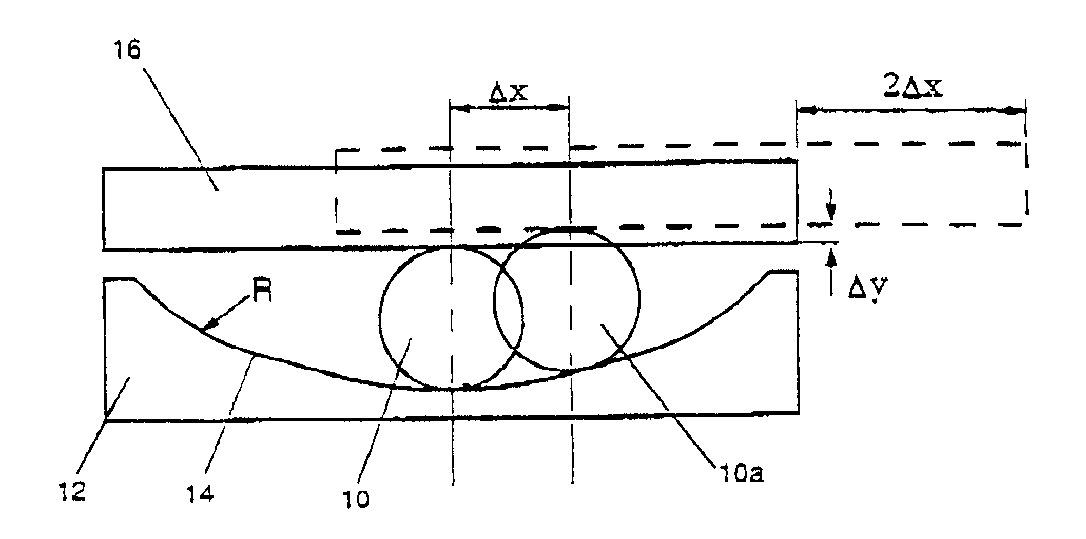
One of the practical impediments to inserting bearings under smaller structures to isolate them seismically is the need to allow for sufficient travel of the structure in relation to the foundation so that damping can take place. In FIG. 1 there is illustrated a lower seat 12 with a curved upper surface 14 upon which a ball 10 rests. For the purposes of this illustration ball 10 is not deformed, whereas in the embodiment according to the invention ball 10 is deformed. A structure 16 or a portion of a structure 16 rests on top of ball 10. As structure 16 is moved from left to right to the position shown in ghost in FIG. 1, ball 10 moves to the position 10a up the curve of surface 14 of radius R. Because each of the top and bottom of ball 10 is in contact with a surface the net effect on member 16 is that it will have moved horizontally a distance 2.DELTA.x as illustrated at the same time that ball 10a has moved horizontally a distance .DELTA.x and vertically a distance .DELTA.y. The ...


PUM


Abstract

The invention described is a system for seismic isolation or vibration of structures which is simple, relatively inexpensive and readily used for smaller structures. It involves use of bearings comprising a ball (10) and ball seats (12, 18) interposed between the structure and its foundation. Either the ball itself (24) or the seat surface (15) on which it rolls is compressible, the resistance to that compression providing a frictional braking force resisting rolling of the ball. This serves to dampen relative movement between the structure and its foundation. There are described several alternative constructions of the friction ball which is the preferred central element in the bearing device. There may be a plurality of balls (44, 47) in each combination of balls and seats.

Description

This invention relates to a frictional braking device. More particularly it relates to a friction ball primarily intended to be used in seismic and vibration isolation.Seismic isolation involves isolating structures and damping the isolated structures from incoming forces due to earthquakes. New Zealand Patent 178949 describes a very successful bearing which may be used to isolate structures in this way. The favoured embodiment of this invention is referred to as a lead rubber bearing. A more comprehensive discussion of seismic isolation and the lead rubber bearing can be found in "An Introduction to Seismic Isolation", Skinner et, John Wylie and Sons (1993).Another means of seismically isolating structures is a bearing sold under the trade mark "Frictional Pendulum" by Earthquake Protection Systems Inc, of Alameda, Calif., USA. Such a bearing consists of a pendulum member with a frictional surface at the distal end of the pendulum member which slides over a polished surface. This i...

Claims


Application Information

Patent Timeline
Patent Type & Authority Patents(United States)
IPC IPC(8): E02D27/34E02D31/08E02D31/00E04H9/02E04B1/36F16F15/02F16F15/04
CPCE02D27/34E02D31/08E04H9/023F16F7/015
Inventor ROBINSON, WILLIAM HENRY
Owner ROBINSON SEISMIC
Why Eureka
Try Eureka