Characterization of organic contaminants and assessment of remediation performance in subsurface formations

a technology of organic contaminants and remediation performance, which is applied in the direction of survey, instruments, borehole/well accessories, etc., can solve the problems of dnapl site characterization, groundwater supply contamination, and quantitative removal

Inactive Publication Date: 2001-11-27
BOARD OF RGT THE UNIV OF TEXAS SYST
View PDF12 Cites 38 Cited by
  • Summary
  • Abstract
  • Description
  • Claims
  • Application Information

AI Technical Summary

Problems solved by technology

Once in the subsurface, these liquids dissolved and caused the contamination of ground-water supplies and then proved resistant to their quantitative removal by the remedial approaches available.
However, their toxicity is often such that their solubilities are many times the permitted maximum contaminant levels allowed by the U.S. Environmental Protection Agency in drinking water.
In addition, NAPLs have become the focus of this concern because of the extreme difficulty in detecting their presence.
This situation has resulted in substantive problems for DNAPL site characterization, in particular because of the tendency of DNAPLs, due to their density and viscosity, to migrate both vertically and laterally from their point of entry into the subsurface to considerable depth.
Consequently, DNAPLs are "largely undetected and yet are likely to be a significant limiting factor in site remediation" (Huling and Weaver, 1991).
It is now contemplated that one or more problems exist in the area of NAPL remediation, namely the inability to directly measure NAPL location, volume and composition and thereby quantitatively assess the performance of remedial technologies.
Thus, the a

Method used


Image

  • Characterization of organic contaminants and assessment of remediation performance in subsurface formations
  • Characterization of organic contaminants and assessment of remediation performance in subsurface formations
  • Characterization of organic contaminants and assessment of remediation performance in subsurface formations

Examples


example 2

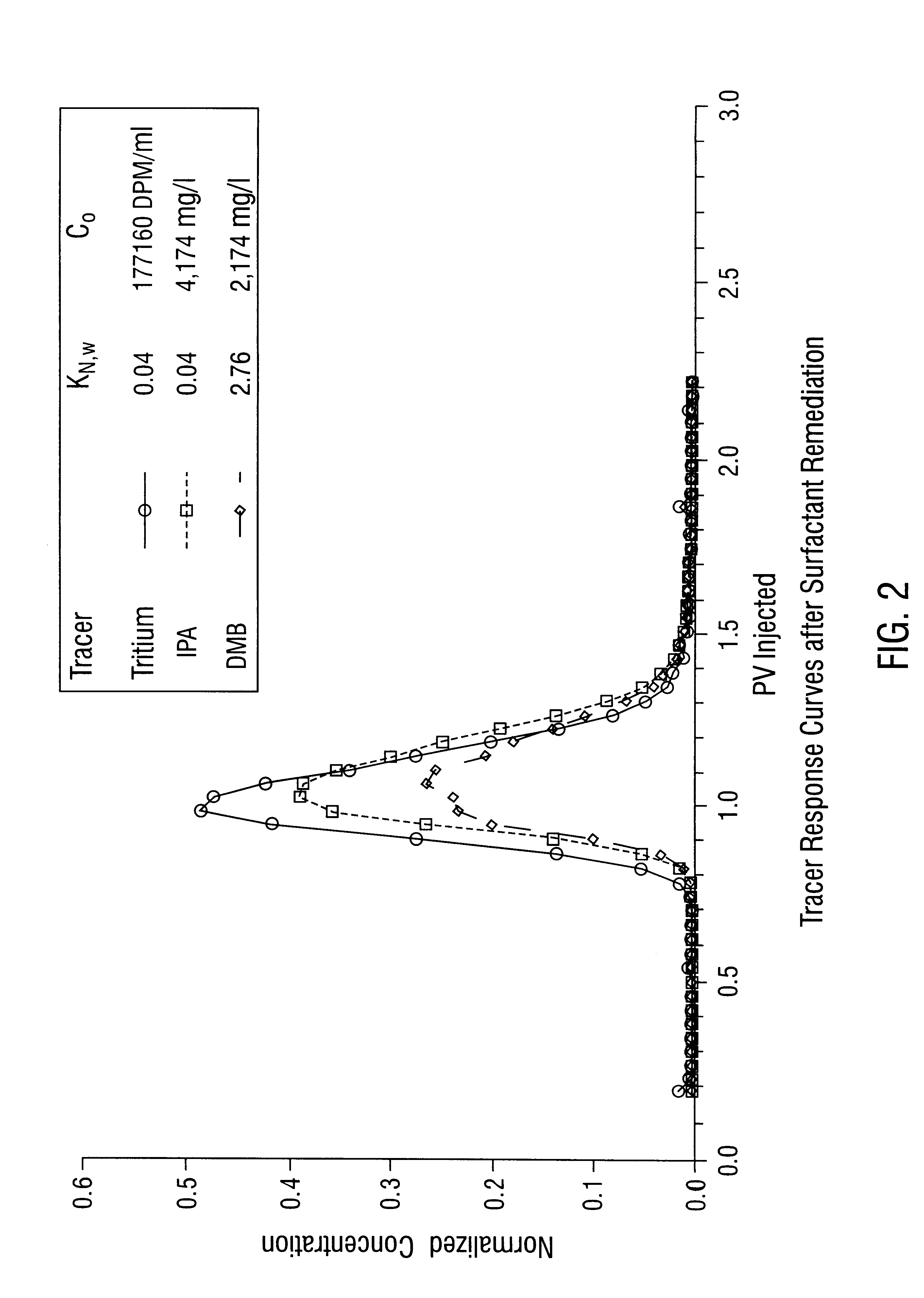
Performance Assessment of a Remediation

The contaminated sand from Example 1 was cleaned by flushing the sand with an aqueous solution of surfactant until all the trichloroethene was removed to thereby simulate a successful remediation. The procedure of Example 1 was then repeated. The results are shown in FIG. 2. Since no NAPL is present in which DMB can partition into, the IPA and DMB travel through the sand at the same rate and, accordingly, FIG. 2 shows overlap of breakthrough curves of the IPA and DMB. Thus, the absence of NAPL in the sand can be inferred, thereby indicating a successful remediation.
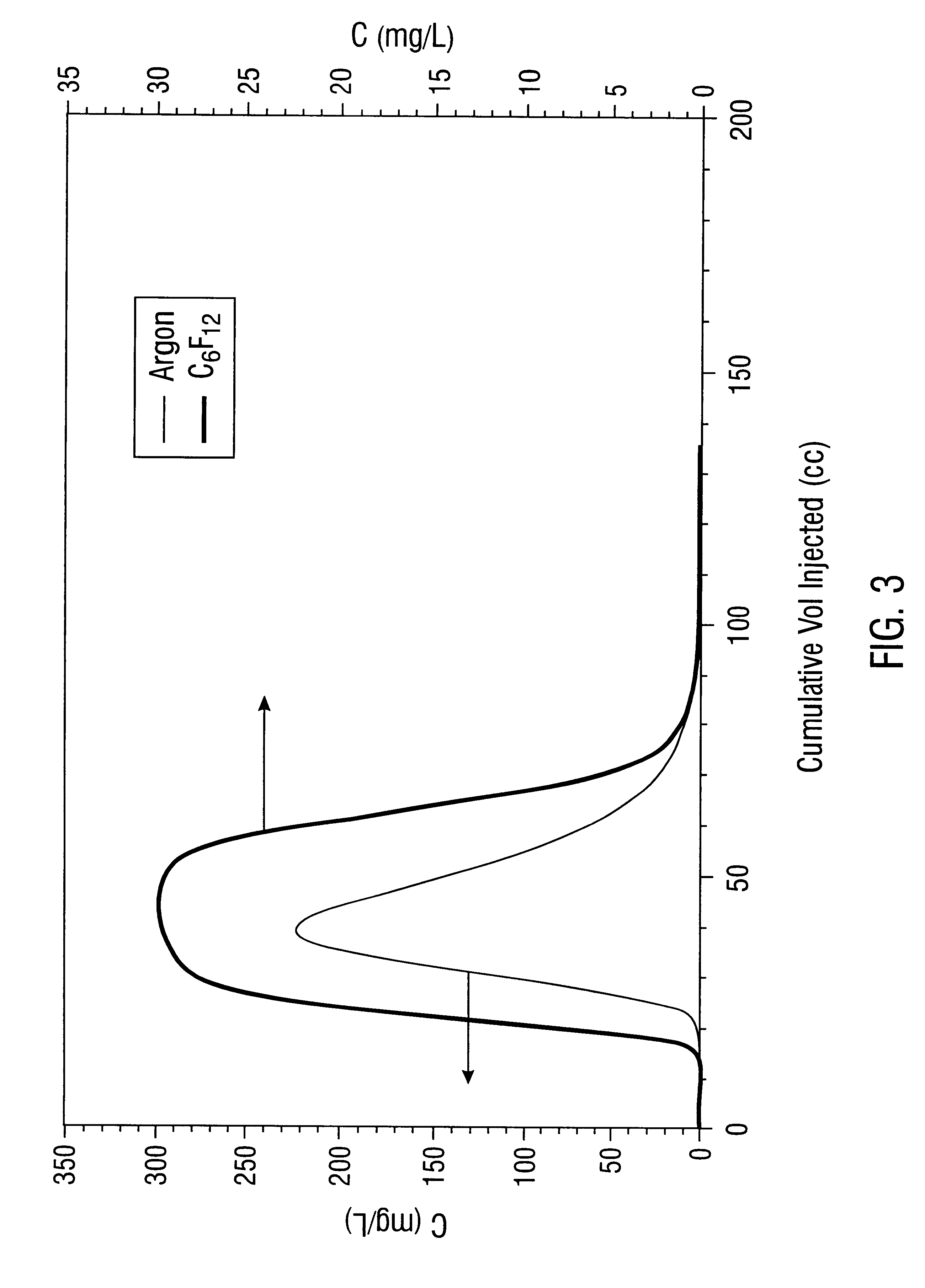
example 3

Use of Tracers to Determine Presence and Volume of DNAPL in Unsaturated Sand

The perfluorocarbon tracers (PFTS) used in this Example were purchased from PCR, Inc. Table 1 lists some of the properties of the selected PFTs as well as those of the other two gases of interest.

The NAPL used to examine the partitioning of perfluorocarbon gases was trichloroethylene (TCE, Certified ACS) obtained from Fisher Scientific. The density of TCE at 20.degree. C. is 1.462 g / cc. Its molecular weight is 131.39 g / mole and its vapor pressure is 1.16 psi at 20.degree. C.

Ottawa sand, purchased from U.S. Silicon, was used in this experiment. The sand has a size range from 40 to 140 U.S. sieve numbers or 0.425 to 0.105 mm. The sand was washed with hydrochloric acid (4N) and baked for 24 hours to remove fine materials and possible organics.

Column Procedures

Three columns were prepared for each experiment: (1) a contaminated primary column (2.5 cm.times.30 cm) saturated with residual water and TCE; (2) a conta...


PUM


Abstract

Characterization of organic contaminants in subsurface formation is performed by methods for detecting the presence of nonaqueous phase liquid in a subsurface formation, and for determining the composition and for determining the volume of nonaqueous phase liquids. Generally the methods comprise introducing one or more partitioning tracers and one or more non-partitioning tracers at one or more injection points located in the subsurface formation and measuring separation between the one or more partitioning tracers and the one or more non-partitioning tracers from one or more sampling points located in the subsurface formation to determine presence, composition and/or volume of nonaqueous phase liquid in the subsurface formation. In addition, the methods can be used to assess the performance of an attempted remediation.

Description

This invention concerns methods of detecting the presence of contaminants located in subsurface formations, methods of determining the composition and / or volume of the contaminants and methods of assessing the performance of remediation designed to treat or remove contaminants from subsurface formations.BACKGROUND OF INVENTIONIn the 1980's, it became apparent that many hazardous waste sites had received organic liquids, such as petroleum hydrocarbons, chlorinated solvents, creosote solutions and coal tars which had subsequently migrated into the subsurface beneath these sites. Once in the subsurface, these liquids dissolved and caused the contamination of ground-water supplies and then proved resistant to their quantitative removal by the remedial approaches available. These liquids are known to environmental scientists and engineers as non-aqueous phase liquids, or "NAPLs". NAPLs such as petroleum hydrocarbons, which are lighter than water, are identified as "ILNAPLs", while those ...

Claims


Application Information

Patent Timeline
IPC IPC(8): B09C1/00E21B49/00E21B47/10E21B49/08G01N33/24
CPCB09C1/00E21B47/1015E21B49/08G01N33/24B09C2101/00E21B47/11
Inventor POPE, GARY A.JACKSON, RICHARD E.
Owner BOARD OF RGT THE UNIV OF TEXAS SYST
Why Eureka
Try Eureka